
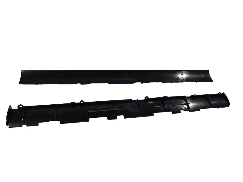
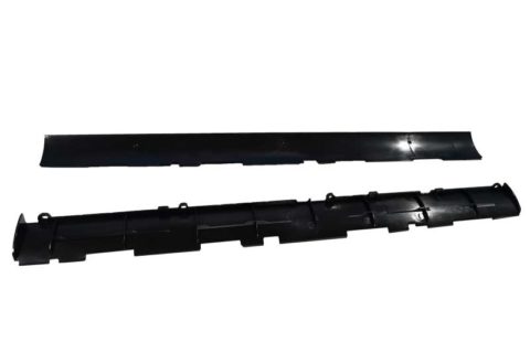
INJECTION MOULDING
Injection moulding parts and injection tools. Full solutions from design to production.
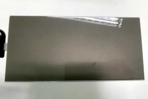
Precision Clean Room Plastic Injection Molding Services - clean room injection m
Author:gly Date: 2024-10-15
The MK6 represents the 6th generation of JETMASTER Series Servo Drive injection molding machines. Clamping mechanism, machine base, and injection... More
If you hover the mouse cursor over any of the part’s faces, it will give you a dynamic update of the draft on the face you are over. Exiting the command also allows the colors to stay displayed on the part. This makes it easy for you to make any changes to the part and see the colors update as you make changes.
Check back next week for part two of our SOLIDWORKS blog series when we look at tips for improving DFM on machined parts.
Luckily, the accessibility of 3D CAD in recent years has brought a multitude of checking tools to “spell check” your design based on DFM rules. Note that specific guidelines such as recommended draft angles or wall thickness are manufacturer dependent. But using these tools can reduce manufacturing costs, a lot of back and forth with the shop floor, time to market, and even save your reputation as a good engineering designer.
The third check in SOLIDWORKS for injection molding is Undercut Analysis. More undercuts mean a more complex multipart tool rather than a simple two-piece tool. More complexity means more added expense and manufacturing time because of features like side-actions. Undercut Analysis is right beneath Draft Analysis and once again, select the pull direction for the option to use the adjustment triad if you haven’t explored all possibilities yet. To make it easier to see these undercut faces, you can toggle the display of each type of face by clicking the hide/show Eye icon next to each face type.
Reliable production is acheived using our JM320-MK6e Toggle Type Plastic Injection Molding Machines with our MK6 servo drive technology and controlled with the CPC6.0 controllers. The process runs in a 2 cavity mold, fully automatic mode with a cycle time of 29sec. The customer is very satisfied that our Injection Molding solutions have easily proved equal to the task of meeting the exacting requirements of high end manufacturing.
Ms. Lai Yuen CHIANG, Chairman and CEO of Chen Hsong Earns “GBA Outstanding Women Entrepreneur Award – Supreme Honorable Winner 2023” Title
Tailored specifically to Indian industrial needs, the Mk6.6/SI-“SI” standing for “Superior India”-is a new jewel in Chen Hsong’s crown.... More
When you run it, you need to tell SOLIDWORKS the direction of pull and what angle of draft you want to look for as acceptable. In most situations, 2 degrees is the amount to look for. For shut offs or if there is a texture required on the face, you should apply at least 3 degrees.
Chen Hsong Propels Plastic Industry Forward and Receives Minister’s Acknowledgment at Second Technology Conference in Mumbai, India
The first thing you want to check for is draft. Without that, parts are not going to eject from the mold cleanly and easily. The molding process is typically engineered around speed and volume so the easier the parts come out, the faster they can be produced and the less chance those parts will incur any cosmetic defects.
Get machined parts anodized and chromate plated with our quick-turn finishing option. Eligible materials include aluminum 6061/6082 and 7075.
New Energy – New Generation! Chen Hsong Group signs strategic cooperation agreement with Chinese electric vehicle manufacturer BYD
In our first of three blog posts, let’s take a look at some useful design checks available in SOLIDWORKS for injection molding.
Ms. Lai Yuen CHIANG, Chairman and CEO of Chen Hsong Earns “GBA Outstanding Women Entrepreneur Award – Supreme Honorable Winner 2023” Title
SOLIDWORKS will then highlight positive draft in green, faces requiring draft in yellow, and negative draft in red (assuming they are all set to default colors). When viewing the part from both sides of the direction of pull, it should be all green from one side and all red from the other. Any yellow faces, need draft added.
The Chen Hsong Group has offices and distributors all around the globe. Select your region from below or search our global list of distributors.
This machine series has been replaced and upgraded by our newer series of injection moulding machines.Click here for more details.
Ideal thickness for injection-molded parts varies on material but can be anything from 0.5mm to 25mm, but most engineering plastics fit between approximately 1mm and 4mm.
Of course, if you want to really be sure your injection-molded part is going to successfully be manufactured, go one stage further and simulate it with SOLIDWORKS Plastics. This will highlight many more things all at once versus running individual checks, so running design checks with a full injection mold simulation is the best approach—especially if you want to get your design right early in the development process.
One of the most important aspects of the part design process is design for manufacturing (DFM). A good place to start, as with most things in life, is Wikipedia. It defines DFM as “the process of designing or engineering a product in order to facilitate the manufacturing process in order to reduce its manufacturing costs. DFM will allow potential problems to be fixed in the design phase, which is the least expensive phase in which to address them.”
For extra help, SOLIDWORKS can count all the faces based on whether they are positive, negative, or require draft. To do this, simply click the Face Classification box. If you are not exactly sure the angle of the direction of pull, use the adjustment triad to play around with different pull directions.
Proto Labs, Inc. 5540 Pioneer Creek Dr. Maple Plain, MN 55359 United States P: 877-479-3680 F: 763-479-2679 E: [email protected]
Our digital factories create prototypes and low-volume parts fast, while our manufacturing network, offers advanced capabilities and volume pricing.
To run the Draft Analysis tool in SOLIDWORKS, you will find it on the Evaluate tab of the CommandManager, or if you want to go another route, it can also be found under the drop-down menus in View > Display > Draft Analysis.
For more organic shaped parts, you may want to call upon the gradual transition option, which uses a gradient display rather than discrete colors.
Mark Rushton is a product portfolio manager for SOLIDWORKS, in the Desktop products team, focused on additive manufacturing. He has been involved with 3D CAD and 3D printing for over 15 years in several capacities from research to consulting for the likes of Rolls Royce, GE, JCB, and Dyson.
Couldn’t have said it better myself. Should be pretty straightforward, right? Well, form can often compete with function and design compromises have to be made when factoring in business decisions. Furthermore, the more complex your design become, the more taxing it is to check that every feature is fit to manufacture.
Enter a value based on the overall thickness of the part (what you want the thickness to be). Choosing the Show Thin Regions will color code all the faces of the part thinner than that value. Thin walls means the flow of polymer is restricted and could cause a short shot. Choose the Show Thick Regions radio button and SOLIDWORKS will color code all faces thicker and thinner than the target value. Much like Draft Analysis, hovering the cursor over the model shows the thickness in that spot. If the walls are too thick, you could end up with sink marks or warpage.
Ms. Lai Yuen CHIANG, Chairman and CEO of Chen Hsong Earns “GBA Outstanding Women Entrepreneur Award – Supreme Honorable Winner 2023” Title
Advancements in materials technology have allowed more and more HVAC parts originally composed of metal to be manufactured using plastic injection molding.
Ms. Lai Yuen CHIANG, Chairman and CEO of Chen Hsong Earns “GBA Outstanding Women Entrepreneur Award – Supreme Honorable Winner 2023” Title
In Zhongshan City, a well known appliance manufacturer is producing Air conditioner components such as this horizontal vane made with ABS and manufactured with the JM320-MK6e.
Precisão e Eficiência em Moldagem por Injeção, Máquinas de Precisão com Servo Drive para Desempenho Inigualável 98% de Índice de Repetição... More
The next consideration helps ensure the material flows nice and evenly into the mold. For this to happen, we want as close to constant wall thickness as possible. This can be especially challenging where we add bosses, clips, and ribs. To highlight any problem areas, we can call upon the Thickness Analysis in SOLIDWORKS. This is found on the Evaluate tab of the CommandManager but is also under the Tools drop-down menu.
Tough Black (Loctite Henkel 3843) and Ceramic-Filled (BASF 3280) are two new advanced photopolymer materials now available for 3D printing.
Our helpful design aid demonstrates part features that are too thin or too thick, bad bosses, right and wrong ribs, and other considerations to be mindful of while designing parts for injection molding.
Chen Hsong Propels Plastic Industry Forward and Receives Minister’s Acknowledgment at Second Technology Conference in Mumbai, India


LK-Mould Ltd.,
No.15, JinShen Road, Jin xia District
Changan Town, Dongguan
523850 Guangdong
China

