
INJECTION MOULDING
Injection moulding parts and injection tools. Full solutions from design to production.
A comprehensive introduction to PVC injection molding - molding pvc plastic
Author:gly Date: 2024-10-15
When even the maximum recommended wall thickness is not enough to meet the functional requirements of a part, ribs can be used to improve its stiffness. When designing ribs: â Use a thickness equal to 0.5 Ã main wall thickness
The typical injection molding cycle lasts 15 to 60 seconds, depending on the size of the part and the complexity of the mold. In comparison, CNC machining or 3D printing might require minutes to hours in order to produce the same geometry. Also, a single mold can accomodate multiple parts, further increasing the production capabillities of this manufacturing process.
Parting lines which are visible on the side of a part where the 2 halves of the mold meet. They are caused by tiny misalignments and the slightly rounded edges of the mold.
Quality articles for engineers and designers to learn about Digital Manufacturing. Written by manufacturing experts, curated by Protolabs Network.
To manufacture a mold with small details require longer machining and finishing times. Text is an example of this and might even require specialized machining techniques such as electrical discharge machining (EDM) resulting in higher costs.
Injection molded parts have two sides: the A side, which faces the cavity (front half of the mold) and the B side, which faces the core (back half of the mold). These two sides usually serve different purposes:
Thick sections can lead to various defects, including warping and sinking. Limiting the maximum thickness of any section of your design to the recommended values by making them hollow is essential.
Founded in 1950, Thogus is an established, family-owned custom plastic injection molder and contract manufacturer headquartered in Avon Lake, Ohio.
A good rule of thumb is to increase the draft angle by one degree for every 25 mm. For example, add a draft angle of 3o degrees to a feature that is 75 mm tall. Larger draft angle should be used if the part has a textured surface finish. As a rule of thumb, add 1o to 2o extra degrees to the results of the above calculations. Remember that draft angles are also necessary for ribs. Be aware though that adding an angle will reduce the thickness of the top of the rib, so make sure that your design complies with the recommended minimum wall thickness.
Reducing the wall thickness of your part is the best way to minimize the part volume. Not only does it mean less material is used, but also the injection molding cycle is greatly accelerated.
Learn all you need to know about CNC machining in 25 minutes or less. Whether you are an experienced design engineer or just getting started with manufacturing, this guide is for you.
Tooling costs are constant (starting at $3,000 and up to $5,000). This cost is independent of the total number of manufactured parts, while the material and production costs are dependent on the production volume.
In this guide we touched on everything you need to get started with injection molding - but there’s plenty more to learn. Here are the most useful resources on injection molding and other digital manufacturing technologies if you want to delve deeper.
Find everything you need to know about 3D printing. Whether you are getting started or youâre an experienced user, youâll find this guide packed with useful tips.
Injection molding is widely used today for both consumer products and engineering applications. Almost every plastic item around you was manufactured using injection molding. This is because the technology can produce identical parts at very high volumes (typically, 1,000 to 100,000+ units) at a very low cost per part (typically, at $1-5 per unit).
In Part 2, we list the most important design considerations to keep in mind while designing for injection molding. It Part 5, we’ll also see how you can mitigate the risk by creating physical prototypes of your parts.
All thermoplastic materials can be injection molded. Some types of silicone and other thermoset resins are also compatible with the injection molding process. The most commonly used materials in injection molding are:
When 2 flows meet, small hair-like discolorations may develop. These knit lines affect the parts aesthetics, but also they generally decrease the strength of the part. Parts with abrupt geometry changes or holes are more prone to knit lines.
Hollow out thick sections and use ribs to improve the strength and stiffness of the part Design ribs with max. thickness equal to 0.5x the wall thickness Design ribs with max. height equal to 3x the wall thickness
If sections of different thickness are required, make the transition as smooth as possible using a chamfer or fillet. This way the material will flow more evenly inside the cavity, ensuring that the whole mold will be fully filled.
For lower volume productions (less than 1000 parts), it may be more cost effective to use a secondary operation to complete your injection molded parts. For example, you could drill a hole after molding rather than using an expensive mold with side-action cores.
Best way to deal with the created undercuts: Use a thread with a pitch greater than 0.8 mm (32 threads per inch) For external threads, place them along the parting line
The minimum order volume for injection molding is 500 units. For these quantities, the molds are usually CNC machined from aluminum. Aluminum molds are relatively easy to manufacture and low in cost (starting at about $3,000 to $5,000) but can withstand up to 5,000 - 10,000 injection cycles.
A key strength of injection molding is it can produce finished products that need little to no extra finishing. The surfaces of the mold can be polished to a very high degree to create mirror-like parts. Or they can be bead blasted to create textured surfaces. The SPI standards dictate the level of finishing that can be achieved.
We’ve collected some examples of products commonly manufacturing with injection molding to help get a better understanding of what can be achieved with this manufacturing process.
There are 3 ways to add fasteners to an injection molded part: by designing a thread directly on the part, by adding a boss where the screw can be attached, or by including a threaded insert.
Parts with different geometries can also fit in the same mold (remember, the model airplane example). This is a great solution for reducing the overall cost of assembly.
One of the biggest benefits of injection molding is how easily complex geometries can be formed, allowing a single part to serve multiple functions.
To recognize them, look out for these 3 things: a parting line, witness marks on the hidden side and a relatively uniform wall thickness throughout the part.
Below is a quick rundown of the key advantages and disadvantages of injection molding to help you understand whether it’s the right solution for your application.
Stripping undercuts (also known as bumpoffs) can be used when the feature is flexible enough to deform over the mold during ejection. Stripping undercuts are used to manufacture the threads in bottlecaps. Undercuts can only be used under the following conditions:
Use a uniform wall thickness within the recommended values When different thickness are required, smoothen the transition using a chamfer or fillet with length that is 3x the difference in thickness
The simplest way to deal with an undercut is to move the parting line of the mold to intersect with it. This solution is suitable for many designs with undercuts on an external surface. Don’t forget to adjust the draft angles accordingly.
Many plastic packaging products are injection molded. In fact, packaging is the largest market for injection molding. For example, bottle caps are injection molded from Polypropylene. Polypropylene (PP) has excellent chemical resistance and is suitable to come in contact with food products. On bottle caps, you can also see all the common unavoidable injection molding imperfections (parting line, ejector marks etc.) and common design features (ribs, stripping undercuts etc.).
Many sterilizable and biocompatible materials are available for injection molding. Medical grade silicone is one of the more popular materials in the medical industry. Silicone is a thermoset though, so special machinery and process control are required, increasing the cost. For applications with less strict requirements other materials, like ABS, polypropylene (PP) and Polyethylene (PE), are more common. Learn more about medical device manufacturing â
Side-action cores are moving elements that enter the mold from the top or the bottom and are used to manufacture parts with overhangs (for example, a cavity or a hole). Side-actions should be used sparingly though, as the cost increases rapidly.
Add a draft angle to the vertical walls of your snap-fit joints Design snap-fits with thickness greater than 0.5x the wall thickness Adjust their width and length to control their deflection and permissible force
On the far side of an injection molding machine is the clamping system. The clamping system has a dual purpose: it keeps the 2 parts of the mold tightly shut during injection and it pushes the part out of the mold after it opens.
An additive that is commonly used to improve the stiffness of the injection molded parts is fiberglass. The glass fibers can be mixed with the pellets at ratios of 10%, 15% or 30%, resulting in different mechanical properties. Colorant can be added to the mixture (at a ratio of about 3%) to create a great variety of colored parts. Standard colors include red, green, yellow, blue, black and white and they can be mixed to create different shades.
Side-action cores and the other in-mold mechanisms can increase the cost of tooling by 15% to 30%. This translates to a minimum additional cost for tooling of approximately $1,000 to $1,500.
In comparison, parts made in a desktop 3D printer can be ready for delivery overnight, while industrial 3D printing systems have a typical lead time of 3-5 days. CNC machined parts are typically delivered within 10 days or as fast as 5 days.
In some cases, the main body of 2 parts of an assembly is the same. With some creative design, you can create interlocks points or hinges at symmetrical locations, essentially mirroring the part. This way the same mold can be used to manufacture both halves, cutting the tooling costs in half.
While these estimates are helpful in some circumstances, they don’t account for everything. After all, tooling doesn’t cap out after 1 million shots. Some of the tools here at Thogus run over a million shots annually; some have reached above 20 million shots before needing replacement.
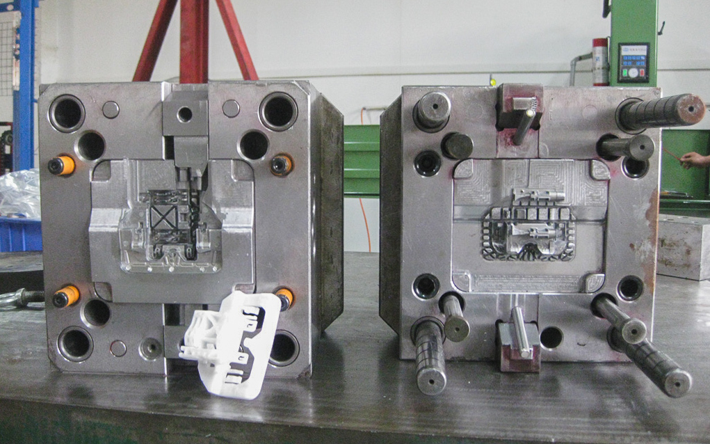
 The image below shows the mold used to manufacture both sides of the casing for a remote controller. Quick quiz: try to locate the *core* (A-side), the *cavity* (B-side), the runner system, the ejector pins, the side-action core and the air vents on this mold.
For smaller productions (1,000 to 10,000 units), the cost of tooling has the greatest impact on the overall cost (approximately 50-70%). So, it’s worthwhile altering your design accordingly to simplify the process of manufacturing of the mold (and its cost).
The team at Thogus is made up of tooling experts who work with high-quantity projects and who know the ins and outs of tool maintenance. Success starts at the beginning: properly build tooling is one of the four pillars in our Manufacturing by Design process. Our expertise carries through to our in-house tooling maintenance, recommending improvements, and tooling and mold transfers. Learn more here.
High-performance engineering thermoplastic with excellent strength and thermal & chemical resistance. Used to replace metal parts.
But compared to other technologies, the start-up costs of injection molding are relatively high, mainly because custom tooling is needed. A mold can cost anywhere between $3,000 and $100,000+, depending on its complexity, material (aluminum or steel) and accuracy (prototype, pilot-run or full-scale production mold).
In most cases, straight-pull molds are preferred, as they are simple to design and manufacture, keeping the total cost relatively low. There are some design restrictions though: the part must have a 2.D geometry on each side and no overhangs (i.e. areas that are not supported from below).
When certain sections cool (and as a result shrink) faster than others, then the part can permanently bend due to internal stresses. Parts with non-constant wall thickness are most prone to warping.
Injection molding is an established manufacturing technology with a long history, but it’s constantly being refined and improved with new technological advancements.
Use a uniform wall thickness throughout the part (if possible) and avoid thick sections. This is essential as non-uniform walls can lead to warping or the part as the melted material cools down.
Bosses are very common in Injection Molded parts and are used as points for attachment or assembly. They consist of cylindrical projections with holes designed to receive screws, threaded inserts, or other types of fastening and assembly hardware. A good way to think of a boss is as a rib that closes on itself in a circle. Bosses are used as points of attachment or fastening (in conjuction with self-tapping screws or threaded inserts).
The purpose of the injection unit is to melt the raw plastic and guide it into the mold. It consists of the hopper, the barrel, and the reciprocating screw.
Injection molding is so popular, because of the dramatically low cost per unit when manufacturing high volumes. Injection molding offers high repeatability and good design flexibility. The main restrictions on Injection Molding usually come down to economics, as high initial investment for the mold is required. Also, the turn-around time from design to production is slow (at least 4 weeks).
This step is essential for launching a successful product. This way design errors can be identified early, while the cost of change is still low.
Learn how to design the most common features encountered in injection molded parts with these practical guidelines. Use them to improve the functionality of your designs, while still complying with the basic design rules.
Almost every plastic component in the interior of a car was injection molded. The 3 most common injection molding materials used in the automotive industry are Polypropylene (PP) for non-critical parts, PVC for its good weather resistance and ABS for its high impact strength. More than half of the plastic parts of a car are made from one of these materials, including the bumpers, the interior body parts and the dashboards.
To make the ejection of the part from the mold easier, a draft angle must be added to all vertical walls. Walls without a draft angle will have drag marks on their surface, due to the high friction with the mold during ejection. A minimum draft angle of 2° is recommended. Larger draft angles (up to 5o °) should be used on taller features. Learn more about the importance of draft angles in this article â
Injection molding typically produces parts with tolerances of ± 0.250 mm (0.010"). Tighter tolerances are feasible in certain circumstances (down to ± 0.125 mm - and even ± 0.025 mm), but they increase the cost drastically. For small production runs (< 10,000 units), consider using a secondary operation (such as drilling) to improve accuracy. This ensures the correct interference of the part with other components or inserts (for example, when using press fits).
The runner system is the channel that guides the melted plastic into the cavity of the mold. It controls the flow and pressure with which the liquid plastic is injected into the cavity and it is removed after ejection (it snaps off). The runner system usually consists of 3 main sections:
They can be also reinforced with fibers, rubber particles, minerals or flame retardant agents to modify their physical properties. For example fiberglass can be mixed with the pellets at ratios of 10%, 15% or 30% resulting in parts with higher stiffness.
The five PLASTICS mold classifications are 101, 102, 103, 104 and 105, with Class 101 being the highest quality, cycles, and production levels, and 105 being the lowest quality, cycles, and production levels. Because wear and tear are side effects of mechanical processes, these estimates are based on injection molding shots (the number of times that mold is filled and opened), not on parts that are produced.
Once your design ready and optimized for injection molding, whatâs next? In this section we’ll take you through the steps needed to start manufacturing with injection molding.
For larger volumes to full-scale production (10,000 to 100,000+ units), the contribution of the tooling costs to the overall cost is overshadowed by the material and production costs. So, your main design efforts should focus on minimizing both the volume part and the time of the molding cycle.
Almost every plastic part around you was manufactured using injection molding: from car parts, to electronic enclosures, and to kitchen appliances.
Most defects in injection molding are related to either the flow of the melted material or its non-uniform cooling rate during solidification.
When the interior of a part solidifies before its surface, a small recess in an otherwise flat surface may appear, called a sink mark. Parts with thick walls or poorly designed ribs are most prone to sinking.
As the plastic shrinks, it applies pressure on the mold. During ejection, the walls of the part will slide and scrape against the mold, which can result to drag marks. Parts with vertical walls (and no draft angle) are most prone to drag marks.
Lego bricks are one of the most recognizable examples of injection molded parts. They’re manufactured using molds, like the one in the picture, which produced 120 million lego bricks (that’s 15 million cycles) before it was taken out of commission. The material used for Lego bricks is ABS because of its high impact resistance and excellent moldabillity. Every single brick has been designed to perfection, achieving tolerances down to 10 micro meters (or a tenth of a human hair). This is partly achieved by using the best design practices, which we’ll examine in the next section (uniform wall thickness, draft angles, ribs, embossed text etc.).
Typically, injection molding will produce parts with tolerances of ± 0.500 mm (0.020ââ). Tighter tolerances down to ± 0.125 mm (0.005ââ) are also feasible in certain circumstances. This level of accuracy is enough for most applications and comparable to both CNC machining and 3D printing.
In this guide you’ll find everything you need to know about injection molding. Master the technology’s basic principles and learn actionable design tips fast that will save you time and cut costs.
The teeth of a thread or the hook of a snap-fit joint are examples of undercuts. Here some ideas to help you deal with undercuts:
There are several factors that may affect the quality of the final product and the repeatability of the process. To yield the full benefits of the process, the designer must follow certain design guidelines. In this section, we outline common defects of injection molding and basic and advanced guidelines to follow when designing parts, including recommendations for keeping the costs to a minimum.
The mold is like the negative of a photograph: its geometry and surface texture is directly transferred onto the injection molded part. It usually makes up the largest portion of the start-up costs in injection molding: the cost of a typical mold starts at approximately $2,000-5,000 for a simple geometry and relatively small production runs (1,000 to 10,000 units) and can go upwards to $100,000 for molds optimized for full-scale production (100,000 units or more). This is due to the high level of expertise required to design and manufacture a high-quality mold that can produce accurately thousands (or hundreds of thousands) of parts. Molds are usually CNC machined out of aluminum or tool steel and then finished to the required standard. Apart from the negative of the part, they also have other features, like the runner system that facilitates the flow of the material into the mold, and internal water cooling channels that aid and speed up the cooling of the part. Learn more about CNC machining in the manufacturing and design guide â Recent advances in 3D printing materials have enabled the manufacturing of molds suitable for low-run injection molding (100 parts or less) at a fraction of the cost. Such small volumes were economically unviable in the past, due to the very high cost of traditional mold making.
For best results: Use embossed text (0.5 mm height) instead of engraved texted Use a font with uniform thickness and a minimum font size of 20 points Align the text perpendicular to the parting line Use a height (or depth) greater than 0.5 mm
Thermoplastic with high impact strength and good mechanical properties & hardness. Suitable for molding parts with thick walls.
All thermoplastics can be injection molded. Some thermosets and liquid silicones are also compatible with the injection molding process.
At this stage, the typical cost per part varies between $1 and $5, depending on the geometry of your design and the selected material. The typical lead time for such orders is 6-8 weeks.
Sliding side-actions and cores are used when it is not possible to redesign the injection molded part to avoid undercuts. Side-action cores are inserts that slide in as the mold closes and slide out before it opens. Keep in mind that these mechanisms add cost and complexity to the mold. Follow these guidelines when designing a side actions:
Thermoset with excellent heat & chemical resistance and customizable shore hardness. Food-safe and medical grade available.
The simplest mold (the straight-pull mold) consist of 2 halves. Features with undercuts (such as the teeth of a thread or the hook of a snap-fit joint) may not be manufacturable with a straight-pull mold though. This is either because the mold cannot be CNC machined or because the material is in the way of ejecting the part.
Living hinges are thin sections of plastic that connect 2 segments of a part and allow it to flex and bend. Typically these hinges are incorporated in mass-produced containers, such as plastic bottles. A well-designed living hinge can last for up to a million cycles without failure. The material used to injection mold a living hinge must be flexible. Polypropylene (PP) and Polyethylene (PE) are good choices for consumer application and Nylon (PA) for engineering uses.
The simplest mold is the straight-pull mold. It consist of 2 halves: the cavity (the front side) and the core (the back side).
Undercuts always add cost and complexity, as well as maintenance to the mold. A clever redesign can often eliminate undercuts.
The typical unit cost at this stage varies between a few cents to $1 and the typical lead time is 4 to 6 months, due to the complexity of designing and manufacturing the mold.
At the point where the runner system connected with the part, a small imperfection is usually visible, called the vestige. If the presence of the vestige is not desirable for aesthetic purposes, then in can also be “hidden” in the functional B-side of the part.
Text is a very common feature that can be useful for logos, labels, warnings, diagrams and instructions, saving the expense of stick-on or painted labels. When adding text, choose embossed text over engraved text, as it’s easier to CNC machine on the mold and thus more economical.
The Society of Plastics Industry (SPI) explains several standard finishing procedures that result in different part surface finishes.
Engineering thermoplastic with excellent mechanical properties and high chemical & abrasion resistance. Susceptible to moisture.
In the mid 1950s, the invention of the reciprocating screw single-handedly revolutionized the plastics industry. The reciprocating screw solved key issues with uneven heating of the plastic that previous systems faced, and opened up new horizons for the mass production of plastic parts.
Blend of two thermoplastics resulting in high impact strength, excellent thermal stability, and high stiffness. Vulnerable to solvents.
Specific guidelines on designing snap-fit joints is a big subject that goes beyond the scope of this article. For more detailed information, please refer to this article from MIT. For best results:
Injection molding is the most cost-competitive technology for manufacturing high volumes of identical plastic parts. Once the mold is created and the machine is set up, additional parts can be manufactured very fast and at a very low cost.
The recommended minimum production volume for injection molding is 500 units. At this point economies of scale start to kick-in and the relatively high initial costs of tooling have a less prominent effect on the unit price.
A well-designed hinge is shown below. The recommended minimum thickness of the hinge ranges between 0.20 and 0.35 mm, with higher thicknesses resulting in more durable, but stiffer, parts.
In 1869, John Wesley Hyatt invented celluloid, the first practical artificial plastic intended to replace ivory for the production of… billiard balls! Early injection molding machines used a barrel to heat up the plastic and a plunger to inject it to the mold.
The replacement schedule can be affected by a number of factors, from material selection to program requirements and preventative maintenance schedules, so it’s better to know how to identify specific issues in advance that might indicate tooling needs to be replaced, rather than relying on hard and fast rules based on shots or timelines.
Modelling a thread directly on the part is possible, but not recommended, as the teeth of the thread are essentially undercuts, increasing drastically the complexity and cost of the mold (we will more about undercuts in a later section). An example of an injection molded part with a thread are bottle caps.
An injection molding machine consists of 3 main parts: the injection unit, the mold - the heart of the whole process - and the clamping/ejector unit.
The typical turnaround for injection molding varies between 6-10 weeks. 4-6 weeks to manufacture the mold, plus 2-4 more weeks for production and shipping. If design changes are required (something quite common) the turnaround time increases accordingly.
The main economic restriction of injection molding the the high cost of tooling. Since a custom mold has to be made for each geometry, the start-up costs are very high. These are mainly related to the design and manufacturing of the mold which typically costs between $5,000 and $100,000. For this reason, injection molding is only economically viable for productions larger than 500 units.
The parts manufactured with “pilot” aluminum molds have physical properties and accuracy identical to parts manufactured with âfull-scale productionâ tool steel molds.
When tooling reaches end-of-life, program costs typically start creeping up. In addition to monetary costs, watch out for costs related to scrap rates, tool repairs, labor for sorting or other operations, and the chaos that comes from issues like orchestrating returns, line downs, and vendor management.
Also raising the text 0.5 mm above the part surface will ensure that the letters are easy to read. We recommend selecting a bold, rounded font style with uniform line thickness, with a size of 20 points or larger. Some font examples include: Century Gothic Bold, Arial and Verdana.
In this section, we examine the purpose of each of these systems and how their basic operation mechanics affect the end-result of the Injection molding process.
Interesting fact: About 50% of the typical injection molding cycle is dedicated to cooling and solidification. Minimizing the thickness of a design is key to speed up this step and cuts costs.
Donât get confused by the term âpilot runâ. If you only require a few thousand parts, then this would be your final production step.
The plastic with the highest impact strength. High thermal resistance, weather resistance & toughness. Can be colored or transparent.
Undercuts in injection molding are part features that cannot be manufactured with a simple two-part mold, because material is in the way while the mold opens or during ejection.
Smaller parts can be molded faster resulting in a higher production output, making the cost per part lower. Smaller parts also result in lower material costs and reduce the price of the mold.
Parts produced with injection molding have very good physical properties. Their properties can be tailored by using additives (for example, glass fibres) or by mixing together different pellets (for instance, PC/ABS blends) to achieve the desired level of strength, stiffness or impact resistance.
The Injection molding plastic with the lowest cost. Food-safe grades available. Not suitable for mechanical applications.
Before you commit to any expensive injection molding tooling, first create and test a functional prototype of your design.
Here is a list of defects to keep in mind while designing a part for injection molding. In the next section, we’ll see how you can avoid each of them by following good design practices.
Alignment of the different moving parts of the mold is never perfect though. This causes the creation of 2 common imperfections that are visible on almost every injection molded part:
Add a fillet equal to 0.5x the wall thickness to internal corners Add a fillet equal to 1.5x the wall thickness to external corners
Injection molding is a manufacturing technology for the mass-production of identical plastic parts with good tolerances. In Injection Molding, polymer granules are first melted and then injected under pressure into a mold, where the liquid plastic cools and solidifies. The materials used in Injection Molding are thermoplastic polymers that can be colored or filled with other additives.
The injection molding process is highly repeatable and the produced parts are essentially identical. Of course, some wear occurs to the mold over time, but a typical pilot-run aluminum mold will last 5,000 to 10,000 cycles, while full-scale production molds from tool steel can stand 100,000+ cycles.
To improve the strength of hollow section, use ribs to design structures of equal strength and stiffness but reduced wall thickness. A well-designed part with hollow sections is shown below:
Experience the Thogus Difference Connect with us today to discuss your project and to learn more about our capabilities.
In a previous section, we examined ways to deal with undercuts. To keep your production on-budget, avoid using side-action cores and other mechanisms unless absolutely necessary.
Ejector (or witness) marks which are visible on the hidden B-side of the part. They are created because the ejector pins are slightly protruding above or indented below the surface of the mold.
It is recommended to avoid stripping undercuts in parts made from fiber reinforced plastics. Typically, flexible plastics such as PP, HDPE or Nylon (PA) can tolerate undercuts of up to 5% of their diameter.
Avoiding undercuts altogether might be the best option. Undercuts always add cost, complexity, and maintenance requirements to the mold. A clever redesign can often eliminate undercuts. Shut-offs are a useful trick to deal with undercuts on internal regions of the part (for snap-fits) or on the sides of the part (for holes or handles).
Surface finishes can be used to give an injection molded part a certain look or feel. Besides cosmetic purposes surface finishes can also serve technical needs. For example, the average surface roughness (Ra) can dramatically influence the lifetime of sliding parts such as plain bearings. Injection molded parts are not usually post-processed, but the mold itself can be finished to various degrees. Keep in mind that rough surfaces increase the friction between the part and the mold during ejection, therefore a larger draft angle is required.
An example of a part with crush ribs is shown below. Using three crush ribs is recommended to ensure good alignment. The recommended height/radius for each rib is 2 mm. Add a minimum interference of 0.25 mm between the crush rib and the fitted part. Because of the small surface contact with the mold, crush ribs can be designed without a draft angle.
If you look around you right now, you’ll see at least a few products that were manufactured with injection molding. You’re probably looking at one right now actually: the casing of the device you are using to read this guide.
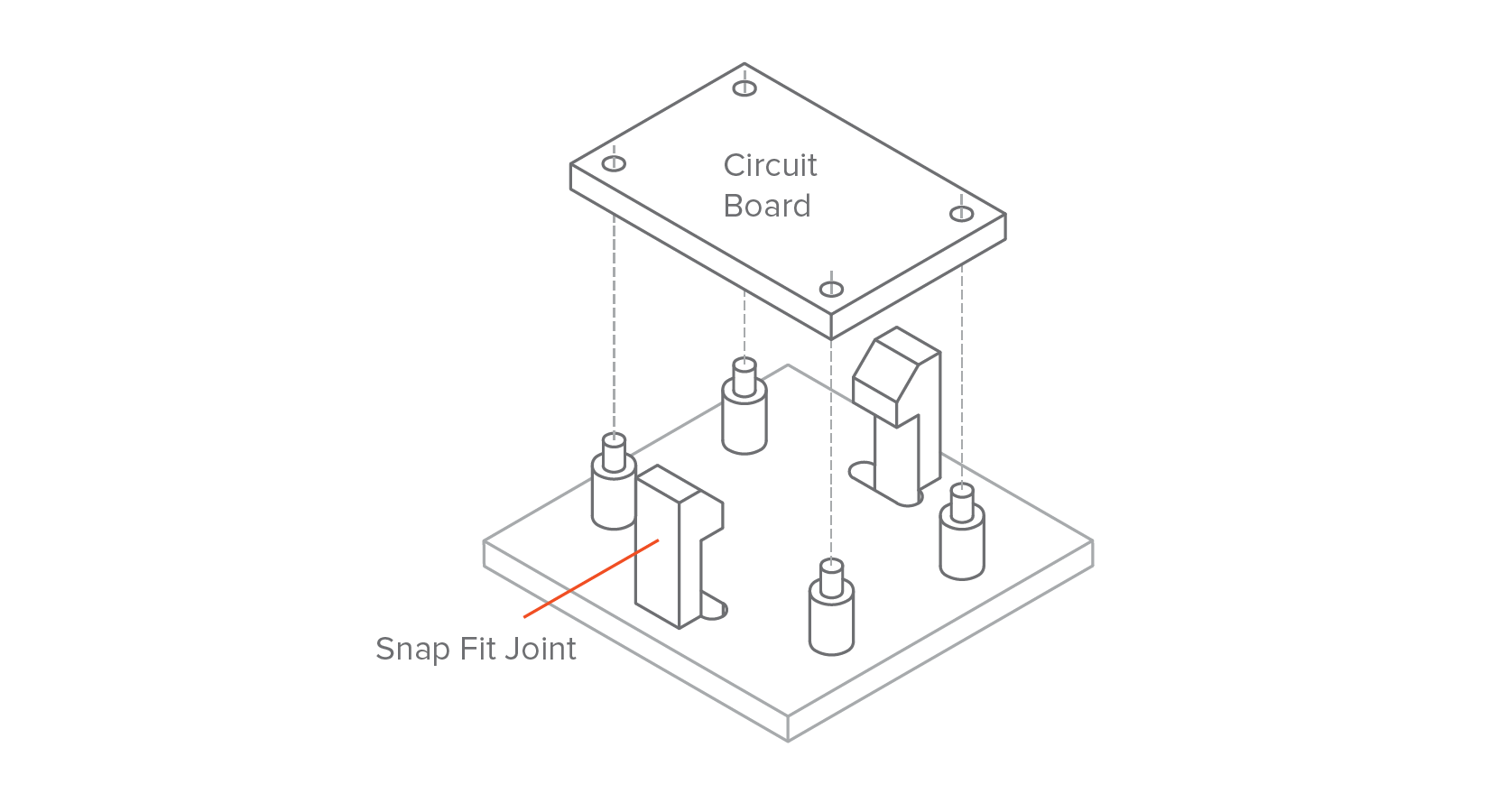
Snap-fit joints are a very simple, economical and rapid way of joining two parts without fasteners or tools. A wide range of design possibilities exists for snap-fit joints. As a rule of thumb, the deflection of a snap-fit joint mainly depends on its length and the permissible force that can be applied on it on its width (since its thickness is more or less defined by the wall thickness of the part). Also, snap-fit joints are another example of undercuts.
The enclosures of almost every mass-produced consumer electronic device was injection molded. ABS and polystyrene (PS) are prefered here for their excellent impact resistance and good electrical insulation.
When producing parts massive quantities of identical parts (from 10,000 to 100,000+ units) then special Injection molding tooling is required.
What is a injection molding? How does it work and what is it used for? In this section, we answer these questions and show you common examples of injection molded parts to help you familiarize yourself with the basic mechanics and applications of the technology.
One of the first signs that tooling needs to be replaced is that parts per million (PPM) trends start to increase. PPM numbers can be higher than expected for a variety of reasons, some of which are just a natural part of the tooling process. However, a sudden rise in PPM in a tooling process that has been smooth sailing is typically due to either tool conditions that cannot be improved or tool conditions that can be repaired temporarily, but then quickly fail.
Tooling that is breaking down causes delays due to greater needs for maintenance and rising PPM rates. When tooling reaches end-of-life, satisfying orders become a burden due to constant downtime. Possible causes of downtime could include waiting on lead times for tool repairs, increased scrap rates, or non-value post-production operations like trimming flash or part sorting.
Trapped air in the mold can inhibit the flow of the material during injection, resulting in an incomplete part. Good design can improve the flowability of the melted plastic. Parts with very thin walls or poorly designed ribs are more prone to short shots.
The most common Injection molding plastic. Excellent chemical resistance. Food-safe grades available. Not suitable for mechanical applications.
Crush Ribs are small protruding features that deform to create friction when different components are pushed together, securing their possition. Crush ribs can be an economical alternative for manufacturing high tolerance holes for tight fits. They are commonly used to house bearings or shafts and other press fit applications.
As we saw in a previous section, fitting multiple parts in the same mold is common practice. Usually, 6 to 8 small identical parts can fit in the same mold, essentially reducing the total production time by about 80%.
After a mold is manufactured, it’s very expensive to modify. Design changes usually require the creation of a new mold from scratch. For this reason, correctly designing a part for injection molding is very important.
Today, injection molding is a $300 billion market. 5+ million metric tons of plastic parts are produced with injection molding globally each year. Recently, the demand of biodegradable materials is increasing for environmental reasons.
Care must be taken through to not overly reduce the stiffness of the part which would downgrade its mechanical performance. Ribs in key locations can be used to increase stiffness.
Engineering thermoplastic with high strength, stiffness & moisture resistance and self-lubricating properties. Relatively prone to warping.
Recommended: 3 Ã wall thickness difference Sometimes sections with different wall thicknesses cannot be avoided. In these cases, use a chamfer or fillet to make the transition as smooth as possible. Similarly, the base of vertical features (like ribs, bosses, snap-fits) must also always be rounded.
Your injection molder or toolmaker can identify at-risk conditions with your tooling, so you should be aware of them throughout the operation. Usually, at-risk conditions are maintained through repairs, but most repairs can only be made so many times before the tooling will need to be replaced. When repairs stop holding, or parts get worn down, it’s time to think about replacing your tooling.
For these volumes, the molds are CNC machined from tool steel and can withstand millions of Injection molding cycles. They are also equipped with advanced features to maximize production speeds, such as hot-tip gates and intricate cooling channels.
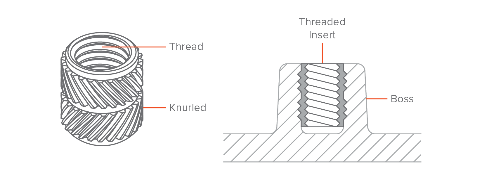
Metal threaded inserts can be added to plastic Injection Molded parts to provide a durable threaded hole for fasteners such as machine screws. The advantage of using inserts is that they allow many cycles of assembly and disassembly. Inserts are installed in Injection Molded parts through thermal, ultrasonic or in-mold insertion. To design a boss that will receive a threaded insert, use similar guidelines as above, using the diameter of the insert as the guiding dimension.
Here, we touched upon all you need to get you started with injection molding. There is plenty more to learn though in our Knowledge Base - a collection of technical articles on all manufacturing technologies, written by experts from Protolabs Network and the manufacturing industry.
Thinner walls mean that the mold can be filled quicker. More importantly, parts thinner parts cool and solidify much faster. Remember that about half the injection molding cycle is spent on the solidification of the part while the machine is kept idle.
Even if we take into account all other possible manufacturing technologies, injection molding with these four materials alone accounts for more than 40% of all plastic parts produced globally every year!
Almost every thermoplastic material (and some thermosets and silicones) can be injection molded. This gives a very wide range of available materials with diverse physical properties to design with.
Learn more about the main cost drivers in injection molding and actionable design tips that will help you reduce the costs of your project.
{{img}}*Example of a living hinge (left) and recommended design dimensions for PP or PE (right)*Before going to full-scale production, prototype your living hinges using CNC machining or 3D printing to determine the geometry and stiffness that best fits your application. Add generous fillets and design shoulders with a uniform wall thickness as the main body of the part to improve the material flow in the mold and minimize the stresses. Divide hinges longer than 150 mm in two (or more) to improve lifetime.For detailed guidelines, please refer to this MIT guide.
Avoid designing bosses that merge into main walls Support bosses with ribs or connect them to a main wall For bosses with inserts, use an outer diameter equal to 2Ã the insert’s nominal size
Without universally accepted guidelines, it can be difficult to figure out when your injection molding tooling needs replaced. The Plastics Industry Association (PLASTICS, formerly the Society of Plastics Industry or SPI) provides standards for mold classification that can help estimate tool life.
Below are some examples of how injection molded parts can be redesigned to avoid undercuts: essentially, material is removed in the area under the undercut, eliminating the issue altogether.
Model airplanes are another common example of injection molded parts. The material used here is mostly Polystyrene (PS), for its low cost and ease of molding. What’s interesting with model airplane kits is that they come with the runner system still attached. So, you can see the path the melted plastic followed to fill the empty mold.
Injection molding is compatible with a wide range of plastics. In this section, you’ll learn more about the key characteristics of the most popular materials. We’ll also discuss the standard surface finishes that can be applied to injection molded parts.
Finishes are usually applied to the mold by hand, which can be an expensive process, especially for high-grade finishes. If your part is not for cosmetic use, donât apply a costly high-grade finish.
The uniform wall thickness limitation also applies to edges and corners: the transition must be as smooth as possible to ensure good material flow. For interior edges, use a radius of at least 0.5 x the wall thickness. For exterior edges, add a radius equal to the interior radius plus the wall thickness. This way you ensure that the thickness of the walls is constant everywhere (even at the corners). Adding to this, sharp corners result in stress concentrations which can result in weaker parts.
Once the mold is manufactured, these complex parts can be reproduced at a very low cost. But changes to the mold design at later stages of development can be very expensive, so achieving the best results on the first time is essential. Follow the guidelines below to avoid the most common defects in injection molding.


LK-Mould Ltd.,
No.15, JinShen Road, Jin xia District
Changan Town, Dongguan
523850 Guangdong
China

