
INJECTION MOULDING
Injection moulding parts and injection tools. Full solutions from design to production.
What are requirements of precision injection molding for ... - precision plastic
Author:gly Date: 2024-10-15
Minerals such as talc and clay are often used as fillers to reduce costs or increase the hardness of finished parts. Because they do not shrink as much as resins do when cooled, they can reduce warping.
Polycarbonate can experience significant shrinkage as it cools after injection. This can lead to dimensional inaccuracies in the final part. To mitigate shrinkage, adjust mold design for compensation, lower melt temperature to reduce cooling rate, and apply proper packing and holding pressure during molding.
Polycarbonate is employed in medical equipment and devices, including IV connectors, housings, and surgical instruments.
PC serves as an excellent electrical insulator, making it suitable for electrical and electronic components. Some other plastics may not provide the same level of electrical insulation.
When choosing a material for a part, relevant properties might include mechanical, physical, chemical resistance, heat, electrical, flammability, and UV resistance. Resin manufacturers, compounders, and independent resin search engines have data online. Here is a quick look at some common commodity and engineering resins.
When designing the gate location for polycarbonate injection molding parts, it’s crucial to prioritize the prevention of weld lines, as they can significantly weaken the part’s structural integrity and harm its aesthetic appearance.
Logos and Text: Textured surfaces, molded part numbers, and company logos look good, but be prepared to pay a bit extra for these and other non-mission critical features. That said, permanent part numbers are requirements for many aerospace and military applications. For text, it is recommended designers: w Use a mill-friendly (san-serif fonts) font such as Century Gothic Bold, Arial, or Verdana. w Keep the font above 20 pt. w Don’t go much deeper than 0.010 to 0.015 in. w Be prepared to increase draft if part ejection is a concern
Polycarbonate supports a variety of surface finishes, including gloss and high-gloss finishes. Matte finishes can reduce glare, making them suitable for control panel overlays. Non-glossy finishes may be preferred for certain applications like screw caps.
Warping, or deformation of the part after molding, can occur due to uneven cooling rates or internal stresses. Prevent warping by ensuring uniform cooling, using mold design features like cooling channels, and implementing post-molding annealing processes.
The injection mold structure and design directly influence various aspects of the final product, including its dimensional accuracy, surface finish,
How to maintain uniform thickness, read our previous blog to get a comprehensive understanding of wall thickness design guidelines.
Polycarbonate injection molding finds applications in various industries. Especially due to its excellent optical clarity, it is used for eyewear lenses, optical discs, and components in the optical industry. Here are some of the applications.
Self-Mating Parts: Identical parts that flip over and mate to themselves are possible and save the cost of a second mold. Elements to let them mate include pegs and holes, interlocking rims, and hooks and latches.
Carbon fiber strengthens and/or stiffens a composite and aids in static dissipation. It has the same limitations as glass fibers. Carbon fiber can make plastic very stiff.
Wall Thickness: The most crucial design requirement for getting good molded parts is to maintain constant wall thickness. They minimize the potential for warped or distorted parts.
Polycarbonate is used in lighting fixtures, including diffusers and lenses, due to its optical properties and resistance to UV radiation.
Designing plastic parts that can be molded has always been important for traditional injection molding processes, but it’s particularly beneficial for parts about to be rapid injection molded (RIM) to ensure speed and quality remain constant during manufacturing. Here’s a look at many of the critical design considerations encountered during rapid injection molding
Draft: Draft (slope the vertical walls) as much as possible to make it easier to eject parts without drag marks or ejector punch marks. Draft also lets designers make deeper features, plus it reduces tool chatter and cosmetic defects when milling deep walls. If you can fit it in, use 1 deg. of draft or more. On core-cavity designs, use 2 deg. or more. A rough rule of thumb is 1 deg. of draft for each of the first 2 in. of depth. From 2 to 4 in. of depth, either 3 deg. of draft or a minimum of 1/8 in. thickness may be required.
With RIM, CAD models are sent directly to the production floor where mold milling begins. In most cases, molds are fabricated from aluminum, not steel. This allows for faster and more cost-effective tooling compared to traditional steel molds.
PC is highly transparent, with optical clarity close to that of glass. This transparency is advantageous for products like lenses, windows, and displays. Many other plastics are not as transparent or may require additional processes to achieve clarity.
If you have any questions regarding injection molding or rapid injection molding, please feel free to call a Protolabs application engineer at (877) 479-3680 or e-mail [email protected].
Bumpoffs: A bumpoff is a small undercut in a part design that can be safely removed from a straight-pull mold without using side-actions. Bumpoffs can solve some simple slight undercuts, but are sensitive to geometry and material.
Tolerances: Molders can generally hold about ±0.003 in. machining accuracy. Shrink tolerance depends mainly on part design and resin choice. It varies from 0.002 in./in. for stable resins such as ABS and polycarbonate to 0.025 in./in. for unstable resins such as TPE. There are techniques for getting the most accuracy out of injection molding. Contact an applications engineer at your injection molder for more information.
Polycarbonate injection molding is a manufacturing process used to create various plastic parts and components from Polycarbonate resin. The process typically includes steps such as material preparation, mold design, machine setup, injection of the molten Polycarbonate, cooling, ejection, quality control, and the repetition of these steps for mass production. Proper control of temperature settings, injection parameters, cooling, and cycle times is essential to achieve consistent and reliable results in PC injection molding.
Polycarbonate is used for automotive components such as headlamp lenses, interior trim, and window glazing due to its impact resistance and lightweight properties.
Polycarbonate injection molding is the process of injecting melted polycarbonate, a tough, transparent, and heat-resistant polymer, into a mold at high pressure and temperature to create complex plastic parts with excellent optical clarity, impact resistance, and mechanical properties. In this post, we will explore the significance and practical applications of PC injection molding, you will learn its process, advantages, common issues, and design principles.
Polycarbonate parts may develop surface defects like blemishes, streaks, or surface haze during molding. Achieve a flawless surface finish by maintaining clean mold surfaces, optimizing processing conditions, and using mold release agents and venting as needed.
Polycarbonate can be sensitive to moisture and high temperatures, potentially leading to hydrolysis and material degradation. Prevent hydrolysis and degradation by thoroughly drying the material, maintaining temperature control, and considering additives or stabilizers to enhance resistance.
Injection molding flow marks are a common injection molding defect. While flow marks generally do not influence the structural integrity
Long glass fibers are used like short glass fibers to strengthen and reduce creep, but make the resin much stronger and stiffer. The downside is that they can be particularly challenging to mold parts that have thin walls and/or long resin flows.
Polycarbonate, often referred to as PC, is a thermoplastic polymer known for its exceptional characteristics. It has gained widespread recognition in various industries due to its impressive combination of physical and chemical properties.
Have you ever noticed a whitening phenomenon in PVC product whitening? Some of your transparent PVC products, like shower curtains
Incorporate a draft angle, typically ranging from 0.5° to 1° per side, to assist with part ejection from the mold. Adjust the draft angle as needed based on part shape and mold design.
Note: These are general guidelines, subject to part geometry and molded construction. Larger parts shouldn’t be designed with the minimum wall thickness. Protolabs’ general rule for wall thickness is 0.040 to 0.140 in.
Selecting Colorants: Stock colors from the resin vendor are typically black and natural. Natural might be white, beige, amber, or another color. Semi-custom colors are created when colorant pellets are added to natural resins. For available colors, check with your injection molder. In some cases, such as at Protolabs, there is no added charge for our inventory colors. But they may not be an exact match and may create streaks or swirls in parts. Custom colors that need to match an exact Pantone or color chip need to be compounded with a resin supplier. This process is slower and more expensive, but produces a more accurate match.
PC exhibits resistance to various chemicals, which makes it suitable for applications in chemically challenging environments. Not all plastics offer the same level of chemical resistance.
From wall thickness and radii to ramps and ribs, here’s a quick look at factors designers and engineers should consider if parts will be injection molded.
Aim for a minimum wall thickness of 0.040 inches (1 mm) and a maximum of 0.150 inches (3.8 mm) for PC parts. This range supports thin walls and complex geometries.
It is used in electronic enclosures, connectors, and components due to its electrical insulating properties and heat resistance.
Core Geometry: Core out parts to eliminate thick walls. You get the same functions in a well molded part. Unnecessary thickness can alter part dimensions, reduce strength, and necessitate post-process machining.
Glass beads and mica flakes stiffen a composite and reduce warping and shrinkage. With high loading, they can be challenging to inject.
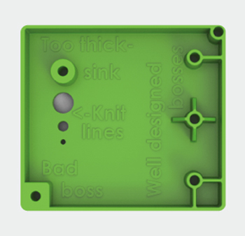
The bosses on the left are poor as they are too thick and might not fill completely, leaving voids. The bosses on the right, however, create strength without having sections that are too thick.
PC is known for its exceptional impact resistance. Compared with other plastic materials, It can withstand significant forces without breaking, making it suitable for applications where durability is crucial.
RIM accommodates side-action and hand-load inserts, as well as simple overmolding and insert molding. Selective use of electrical discharge machining (EDM) can improve mold features such as corners and edges. And several surface finish options are available. All of this lets RIM make parts in a few weeks rather than the months needed for traditional injection molding methods.
Pickouts: A pickout is a separate piece of metal inserted into the mold to create an undercut. It is ejected with the part, then removed by the operator and re-inserted in the mold. Using a pickout lets designers overcome shape and positioning restrictions, but is more costly than sliding shutoffs or using a side-action.
It is used for eyewear lenses, optical discs, and components in the optical industry due to its excellent optical clarity.
Here are the typical ranges for some key PC injection molding process parameters for reference. The specifications parameter number needs to be adjusted depending on PC types and grades.
From left to right, the components of a RIM press include: ram (1), screw (2), hopper (3), barrel (4), heaters (5), materials (6), nozzle (7), mold (8), and part (9).
When designing PC injection molding parts, these guidelines help ensure that PC parts meet end-use requirements and maintain high quality.
Polycarbonate comes in several types or grades. Common grade polycarbonates include Medical-Grade Polycarbonate, Food-Grade Polycarbonate, and Generic-Grade polycarbonate.
Steel Core Pins: These holes can be made with steel core pins in the mold. A steel pin is strong enough to handle the stress of ejection and is smooth enough to release cleanly from the part without draft. There shouldn’t be any cosmetic effect on the resulting part; if there is, it will be inside the hole where it won’t be seen.
PC retains its properties at elevated temperatures, making it suitable for components exposed to heat and thermal stress. This advantage is particularly valuable in applications like automotive lighting and electronics, where heat resistance is required.
Stainless steel fibers are used to control EMI (electromagnetic interference) and RFI (radio frequency interference) typically in housings for electronic components. They are more conductive than carbon fiber.
In summary, Polycarbonate injection molding is a versatile and widely used manufacturing process known for its ability to produce high-quality parts with exceptional properties. If you have a project that could benefit from Polycarbonate injection molding, don’t hesitate to explore its potential. Whether you’re in the automotive, medical, or any other industry, Polycarbonate could be the solution you need. For reliable Polycarbonate injection molding services, consider reaching out to Zhongde, your trusted partner in manufacturing excellence.
Side-Actions: Side-actions form undercuts on the outside of a part. The undercuts must be on or connected to the parting line. They must also be in the plane of the parting line and connected and perpendicular to the direction the mold is opening.
Tab Gates: Thin edges restrict flow and can break during gate trimming. Tab gates give injection molders a thick area to place a gate into your part. There may be alternatives, so please contact the molder’s applications engineers.
Prevent stress concentrations by avoiding sharp corners. Use a corner radius of at least 0.125 inches (3 mm) in PC injection molded parts.
Compared with other plastic injection molding, the polycarbonate injection molding process requires special attention. Our previous blog Principle of Injection Molding Process explains the injection molding process in detail.
When using ribs for additional strength or support, make the rib thickness between 0.5 and 0.6 times the thickness of the adjoining wall. Avoid using rib heights more than three times the thickness.
Polycarbonate finds applications in aircraft interiors, including windows, panels, and interior components, where lightweight and high strength are essential.
The part on the left is the originally designed part. The part on the right has been cored out to reduce part thickness while still being able to perform all of its necessary functions.
Undercuts: An undercut is an area of the part that shadows another area of the part, creating an interlock between the part and one or both mold halves. On the image below, the left image (1) illustrates a clip with an undercut feature. On the right image (2), an access hole beneath the undercut lets the mold protrude through the part and provides the needed latch shutoff geometry.
Optical grade Polycarbonate molded parts are optically clear and have near-total light transmittance and a very low haze factor. UV additives often adapt to PC to protect against direct, long-term exposure to sunlight. By adding flame retardant, polycarbonate can meet the UL 94 standard.
Core-Cavity: When you draft, use core-cavity instead of ribs. It provides constant wall thicknesses rather than walls with a thick base. It also lets machine shops mill molds with better surface finish and deliver better parts faster.
Short glass fibers can be added to a resin to strengthen a composite and reduce creep, especially at higher temperatures. They make the resin stronger, stiffer, and more brittle. They can also cause warp due to the difference in cooling shrink between the resin and fibers.
Radii: Sharp corners weaken parts and create molded-in stress from resin flow. Designers should add radii in sharp corners.


LK-Mould Ltd.,
No.15, JinShen Road, Jin xia District
Changan Town, Dongguan
523850 Guangdong
China

