
INJECTION MOULDING
Injection moulding parts and injection tools. Full solutions from design to production.
What Are My Options For Low Volume Injection Moulding? - low volume injection mo
Author:gly Date: 2024-10-15
Over the years, numerous companies and researchers set out to determine which machine controls to use to eliminate each specific part problem. An example was an Eastman Kodak research project in 1962 to establish how to control specific dimensions in their Instamatic film cartridge. In a design of experiments project, and after six months of molding and measuring, the report concluded that the dimensions were being affected by: barrel zone temperatures, screw RPM, injection pressures, holding time, fill time, and back pressure. In the conclusion, the author states, “all of the above machine settings had an effect on part dimensions and further study would be required”.
It is very important to understand the Velocity to Pressure (VPT) setpoint in order to set up a robust scientific molding process. Not very many years ago, injection molding machines commonly used a hydraulic injection pressure setting and an injection timer to fill...
For decades, the idea that specific machine control settings would directly correlate to specific part problems and their solutions seemed ingrained in the industry. However, that was wrong.
In early 1963, Don Paulson, a professor at the General Motors Institute, began a different approach in his research on the causes of mold part variations. The basic premise was plastic processing had to follow the same laws of physics, as all other processes, and that the molding process was simply a four-step sequence of energy inputs and removals.
There are various dynamic variotherm technologies, including Heat & Cool™, Induction Heating Molding (IHM), and Electricity Heating Mold (E-Mold)… etc. Among these advanced technologies, some increase temperature in the entire moldbase; some increase temperature only on the mold surface. But in reality, mold temperature control mechanism is extremely complex; therefore, performing and managing those variotherm technologies is very challenging in injection molding system.
For decades, the idea that specific machine control settings would directly correlate to specific part problems and their solutions seemed ingrained in the industry. However, that was wrong.
As Ultrabooks continue to take the notebook design trend in “thin and light,” manufacturers are finding ways to keep up with the trend yet reduce production costs. Under such circumstances, the world leading component manufacturer MiTAC Precision Technology has replaced metal chassis with glass fiber reinforced plastics, which not only enables lighter and thinner body but also ensures cost-competitive in comparison to metals. However, glass fiber material might cause floating fibers and welding line problems and further lower product quality. Heat and cool process can help avoid these problems significantly, which utilizes rapid temperature-changing molding process to increase melt fluidity in the filling stage and further improve part quality within a reasonable cycle time.
There was a total of 16 measurements recorded for each cycle. The research continued for four years. Thousands of machine cycles were run and recorded on chart paper to be individually analyzed. Test bars and plaques of various thicknesses were molded and measured. Machine adjustments were made to cause dimensional variations and cause part defects, such as: voids, sink marks, burn marks, and flash. In nearly every case, the defect could be directly attributed to one or more of the four basic plastic processing variables.
In the November 2012 issue of Plastics Technology magazine, there was an excellent article by Kip Doyle in their "Know How" column (John Bozzelli took a well deserved month off). The title of the article was The Top 10 Reasons Why Molders Fail at Implementing...
This blog post continues the Paulson Training series on learning injection molding as a science - Scientific Injection Molding. From the plastic's point of view there are only 4 basic variables in the injection molding process - plastic pressure in the cavity, melt...
The injection molding process for plastic was developed more than 100 years ago. A dynamic growth in all processing methods occurred after World War II. As plastics achieved wider use, it was apparent that production personnel had to learn how to solve part quality and consistency problems. The method used was to determine which of the 20 or so machine controls would solve each type of part problems, e.g. dimensions, weld lines, voids, sink marks, warp, etc. But there seemed to be little or no correlation between machine control settings and most of the molded part problems.

With Moldex3D’s three dimensional transient heat transfer simulation ability, temperature distribution at any specific time can be predicted. Fig. 3 shows the mold temperature cross section view at the filling stage for both cases. Also, by checking the part temperature distribution at the end of filling (EOF), we can observe the temperature increase at weld line locations (Table 1), which is helpful in improving product appearance.

Moldex3D provides an effective way for fast design validations. By predicting transient temperature distribution in three dimensional, users can predict the effects of variotherm technology and avoid potential problems prior to mold making stage. We also would like to share a conference paper, The Effects of Various Variotherm Processes and Their Mechanisms on Injection Molding, which conducted various technologies, including Conventional Injection Molding (CIM), Heat & Cool™, IHM, and Emold by using true 3D transient cool technology.
More and more molders are turning to what has become known as "scientific molding" in an effort to systematize their injection molding processes, make them more controllable and make them easily repeatable. As we mention on this site and in many published articles...
Was browsing through a forum at the Plastics Today website and ran across a thread that brought back memories. Today, Decoupled Molding™" and Scientific Molding are commonplace. But when did these concepts REALLY begin to be used in the injection molding...
This is the third post relating to Paulson injection molding courses and the application of Scientific Molding Packing pressure and gate seal- If you’ve followed our sequence of machine control settings, you’ve learned about fill rate control and the velocity to...
In the past, the training of competent molding personnel has required years of experience on the production floor. This new understanding of molding as a science based technology allows personnel to learn injection molding from the plastic’s point of view and understand the actual causes of part defects. Molders must still learn machine setup, the operation of each machine control and the effects of each machine control on the plastic. The raw material must still be monitored, and the machines must be maintained, but the decisions on best control settings, best cycles and how to solve molded part problems will be science-based. Experience has shown that learning plastic processing from the plastic’s point of view is far faster and more effective than the traditional method.
A family-owned company created in 1971, Paulson Training is a global provider of workforce development solutions for the plastics industry.
By Donald C. Paulson (As published in Plastics Business Magazine) More and more we hear the term Scientific Molding used to describe the ideal injection molding process. But what does it mean exactly? Opinions vary widely. Allow me, as a long-time researcher...
First, the research was proof that plastic processing follows the same physical laws as all other materials, and secondly, the properties and characteristics of the molded parts are determined by the four basic plastic variables.
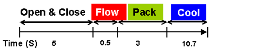
In Moldex3D, the leading plastic injection molding software, variotherm technologies can be simulated and validated with proper settings. In the following case example, Fig. 1 (a) is a CIM cooling channel design and Fig. 1(b) is the steam heating cooling channel. Fig. 2 shows the time sequence of the two different methods. In the CIM process, the water temperature is set at 80℃ at both core and cavity side. Cooling time and cycle time are 10.7 and 19.2 seconds respectively. In the heat/cool process, the water temperature is set at 80℃ at the core side. In order to reach 150℃ on the surface of cavity side, 180℃ steam is set to heat cavity side for 25 seconds in the process. Cooling time and cycle time are 25 and 58.5 seconds respectively.
A molding machine was then instrumented to ensure that each molding cycle could be examined to check for unintended machine or plastic variations. These instruments measured and recorded the machine timers, barrel temperatures, screw travel, screw RPM, back pressure, injection pressures, and clamp force. In the mold, three pressure transducers and thermocouples measured the plastic pressures and the mold temperatures. They also measured fill times.
Each of these molding steps would be governed by the laws of physics. First, the Laws of Heat Transfer; second, the Poiseuille fluid flow law; and third, the Equation of State for Plastic. These three equations applied to the molding process required only four measurements during each molding cycle. Those four measurements are the melt temperature, the fill time, cavity pressure, and the mold temperature.


LK-Mould Ltd.,
No.15, JinShen Road, Jin xia District
Changan Town, Dongguan
523850 Guangdong
China

