soft plastic lure molds 3d models - 3d printed soft plastic mold
Author:gly Date: 2024-10-15
With Prototech Asia, you’ll have easy access to this service. Whether you need a small series of plastic or metal prototypes, we can meet your needs.

Prior to ejection from the mold, injection molded parts are cooled down from manufacturing temperatures so that they hold their shape when ejected. During the part cooling step of the molding process, changes in pressure, velocity and plastic viscosity should be minimized to avoid defects. Few aspects are more crucial during this period than wall thickness. This feature can have major effects on the cost, production speed and quality of the final parts.
The direct or sprue gate is a manually trimmed gate that is used for single cavity molds of large cylindrical parts that require symmetrical filling. Direct gates are the easiest to design and have low cost and maintenance requirements. Direct gated parts are typically less stressed and provide high strength. This gate leaves a large scar on the part at the point of contact.
Contact Prototech Asia today at (+86) 156 0669 3070 or connect with us online to get started turning your concept into a reality.
To create the mold, a prototyping firm might use a common mold base and aluminum. These materials enable the fabrication firm to reduce costs—and the time it takes to produce your prototype.
This method takes advantage of the vacuum effect. During plastic prototype manufacturing, the fabricator will inject material into a silicone mold. You might also hear vacuum casting called silicone molding for this reason.
With the right material, a finished plastic prototype has the robustness and mechanical properties of a final product. Accordingly, project owners can perform tasks as needed.
These type of gates require an operator to separate the parts from the runners manually after each cycle. Manually trimmed gates are chosen for several reasons:
SLA plastic prototyping is a high-precision method for products that require fine detail. Fabricators can use this method to create remarkably thin layers. The layers can measure anywhere from 0.05mm to .10mm in thickness.
The mold or die refers to the tooling used to produce plastic parts in molding. Traditionally injection molds have been expensive to manufacture and were only used in high-volume production applications where thousands of parts were produced. Molds are typically constructed from hardened steel, pre-hardened steel, aluminum, and/or beryllium-copper alloy. Selecting a material for mold building is primarily a question of economics. Steel molds generally cost more to construct but offer a longer lifespan that will offset the higher initial cost over a higher number of parts made before wearing out. Pre-hardened steel molds are less wear-resistant and are primarily used for lower volume requirements or larger components. The hardness of the pre-hardened steel measures typically 38 and 45 on the Rockwell-C scale. Hardened steel molds are heat treated after machining, making them superior in terms of wear resistance and lifespan. Typical hardness ranges between 50 and 60 Rockwell-C (HRC).
Each injection mold design must have a gate, or an opening that allows the molten plastic to be injected into the cavity of the mold. Gate type, design, and location can have effects on the part such as part packing, gate removal or vestige, cosmetic appearance of the part, and part dimensions and warping.
It will also give you a better idea of your requirements for a full production run. Furthermore, a prototype created using this method will allow you to evaluate all the parts you’ll need. In addition, it will lay the foundation for the subsequent mold for your full production run.
Heel Refers to the portion of an automatic custom injection mold that keeps the slide in the forward position when the molding machine is closed on the mold
Prototyping is a powerful tool for businesses and entrepreneurs. It’s a way to assess or present a physical product before going to full-scale production.
Undercuts Refers to the portion of the designed component where a slide or hand pull is required to create holes, windows or clips that are not in the line of draw (#1 in Figure 1 below)
Steel Safe Refers to the amount of metal left on the mold in order to tweak in a dimension. For example, if you have an inside diameter that is supposed to be .500 you may leave the mold at .505 in case you get excessive shrink
You can use a plastic prototype made using this method to perform a visual assessment. You can also use this kind of prototype for marketing validation. You might even use it to perform an ergonomic test.
Yet other resins are less rigid. Still, there are limited material choices when using the SLA plastic prototyping method.
Casting enables fabricators to create high-precision plastic prototypes in fine detail. A silicone mold makes it possible to re-create prototype parts that are identical to the final product.
When the hot melt flows into the injection mold, the thick sections don’t cool as fast as the rest of the part because the thicker material becomes insulated by the outside surface of faster cooling plastic. As the inner core cools, it shrinks at a different rate than the already cooled outer skin. This difference in cooling rates causes the thick section to draw inward and create a sink mark on the outside surface of the part, or worse, completely warp the part. In addition to being unattractive, the mark also represents added stress that is built into the part. Other less conspicuous areas where sink occurs include ribs, bosses and corners. These are often overlooked because neither the feature nor the part itself is too thick; however, the intersection of the two can be a problem.
Cavity Refers to the upper half of the injection mold usually the show surface of the finished product but is mainly concave
If so, creating a plastic prototype is an important part of the early manufacturing process. What’s more, it’s the foundation for a planned production run.
I am Ibrahim from Palladium Company. Our aim is to develop and provide s solutions and services for cell phone, computer networks and information system applications.
We guarantee that our prototype production methods will meet your requirements. They’re even more efficient than 3D printing.
We are looking for a factory that will manufacture mock-ups for our phone case with final finishing, and we are looking for long- term cooperation.
The edge gate is the most common gate design. As the name indicates, this gate is located on the edge of the part and is best suited for flat parts. Edge gates are ideal for medium and thick sections and can be used on multicavity two plate tools. This gate will leave a scar at the parting line.
The CAD model will also show how the various parts of your prototype will fit together. More importantly, it will show how your product will function as a whole.
Resultantly, it cost less, and you can get this kind of project started faster. All you need to get started with CNC plastic prototyping is a CAD rendering.
With a plastic prototype, you can test your design. Before building a prototype, however, you’ll need to formalize the plans for your project.
The largest factor to consider when choosing the proper gate type for your application is the gate design. There are many different gate designs available based on the size and shape of your part. Below are four popular gate designs:
This method allows you to test your concept fast and cost-effectively. At the same time, you don’t have to compromise quality for these benefits.
Choosing the proper wall thickness for your part can have drastic effects on the cost and production speed of manufacturing. While there are no wall thickness restrictions, the goal is usually to choose the thinnest wall possible. Thinner walls use less material which reduces cost and take less time to cool, reducing cycle time.
Injection molding enables fabricators to create a high-quality product quickly. It’s ideal for a highly limited prototype production run.
A fabricator can reuse the silicone mold several times. However, it has a relatively limited service life. During the service life of the mold, however, the fabricator can create a perfect duplication of any part.
Now you know more about how to develop a plastic prototype. You’ve also learned how to gain a competitive advantage, especially if you’re manufacturing goods in China.
Gate Types There are two types of gates available for injection molding; manually trimmed and automatically trimmed gates.
Thick sections take longer to cool than thin ones. During the cooling process, if walls are an inconsistent thickness, the thinner walls will cool first while the thick walls are still solidifying. As the thick section cools, it shrinks around the already solid thinner section. This causes warping, twisting or cracking to occur where the two sections meet. To avoid this problem, try to design with completely uniform walls throughout the part. When uniform walls are not possible, then the change in thickness should be as gradual as possible. Wall thickness variations should not exceed 10% in high mold shrinkage plastics. Thickness transitions should be made gradually, on the order of 3 to 1. This gradual transition avoids stress concentrations and abrupt cooling differences.
A plastic injection rapid tooling is usually manufactured to produce plastic prototypes in the real material. The process for creating a prototype using this method is much like the practice used for a full production run.
The creation of a silicone mold requires a master model. Fabricators may create the master model using 3D machining or 3D printing. They’ll then use the 3D printed object to create the silicone mold.
Line of Draw The direction in which the two custom injection mold halves will separate from the plastic part allowing it to be ejected without any obstructions from metal creating undercuts
Following some basic rules of injection molded part design will result in parts that are easier to manufacture and assemble, and are typically much stronger in service.
Warp Refers to area of a injection molded part that distorts during cooling or molding, causing undesired results in the finished product. Usually caused by un-uniform wall sections
Plastic injection molding works well for fields that require considerable testing and certification. One such industry is the medical sector. With plastic injection molding, you can satisfy regulatory constraints and requirements in this and other fields.
Plastic injection molding is the preferred process for manufacturing plastic parts. Injection molding is used to create many things such as electronic housings, containers, bottle caps, automotive interiors, combs, and most other plastic products available today. It is ideal for producing high volumes of plastic parts due to the fact that several parts can be produced in each cycle by using multi-cavity injection molds. Some advantages of injection molding are high tolerance precision, repeatability, large material selection, low labor cost, minimal scrap losses, and little need to finish parts after molding. Some disadvantages of this process are an expensive upfront tooling investment and process limitations.
The fabricators automate the entire process. The work of the machine is controlled by a computer. The computer will direct the machine using a 3D file.
A fabricator might use one of several resins, including an ABS-like, acrylic, or epoxy material. The resin that you choose for your project will vary depending on your desired visual and mechanical properties.
The first plastic prototype manufacturing method—injection molding—requires an extra step before creating a mockup of your product. As its name implies, your design firm must create a mold before creating your prototype.
Still, fabricators can use CNC machining plastic prototyping with a range of materials. This method is efficient for producing ten or fewer prototypes.
Texturing is a process used to apply patterns to a mold surface. This process allows flexibility in creating the final appearance of your parts. Texturing is an integral piece in overall product development and should be considered during the design process to achieve the desired results. Texture can be a functional component of design (for example, to improve grip), as well as a strategy for camouflaging imperfect or frequently handled parts. Texture can also be used to reduce part wear from friction.
With injection molding, granular plastic is fed by gravity from a hopper into a heated barrel. As the granules are slowly pushed forward by a screw-type plunger, the plastic is forced into a heated chamber called the barrel where it is melted. As the plunger advances, the melted plastic is forced through a nozzle that seats against the mold sprue bushing, allowing it to enter the mold cavity through a gate and runner system. The mold remains at a set temperature so the plastic can solidify almost as soon as the mold is filled.
The minimum wall thickness that can be used depends on the size and geometry of the part, structural requirements, and flow behavior of the resin. The wall thicknesses of an injection molded part generally range from 2mm – 4mm (0.080" – 0.160"). Thin wall injection molding can produce walls as thin as 0.5mm (0.020"). The chart below shows recommended wall thicknesses for common injection molding resins.
Runner A channel cut into custom injection molds, in which plastic travels from the injection molding machine, through the sprue, through the runner and then through the gate ultimately filling the part
Draft Refers to portion of injection molding part that has some taper to make it easier to remove from the mold. Generally all plastic components should be designed with draft where possible
Using this method, a fabricator can create your prototype in as little as two to four weeks. Furthermore, the resulting prototype will likely cost 40% to 60% less compared to a standard mold. Ultimately, the cost and time it takes to create your prototype mold will vary based on the complexity of your product.
These type of gates incorporate features in the tool to break or shear the gates when the tool opens to eject the part. Automatically trimmed gates are used for several reasons:
Aluminum molds cost substantially less than steel molds, and when higher grade aluminum such as QC-7 and QC-10 aircraft aluminum is used and machined with modern computerized equipment, they can be economical for molding hundreds of thousands of parts. Aluminum molds also offer quick turnaround and faster cycles because of better heat dissipation. They can also be coated for wear resistance to fiberglass reinforced materials. Beryllium copper is used in areas of the mold which require fast heat removal or areas that see the most shear heat generated.
Plastic prototype companies inject raw material into the mold using a vacuum bell jar. It will take 30 to 40 minutes for the resulting cast to harden.
A plastic injection mold prototype enables you to experience, in real life, a near-perfect replica of your final product. There are many industries that commonly take advantage of this method. These industries include:
Plastic injection mold prototyping enables fabricators to create high-precision mockups in fine detail. What’s more, they can use the prototyping method to create complex shapes. They can create prototypes for products that range in weight from a few grams to several kilograms.
Gates vary in size and shape depending upon the type of plastic being molded and the size of the part. Large parts will require larger gates to provide a bigger flow of resin to shorten the mold time. Small gates have a better appearance but take longer to mold or require higher pressure to fill correctly.
You can also use this method to create a transparent part. Furthermore, you can create a wide range of finishes once your prototype part is complete.
This practice is important because it allows you to work with a physical representation of your product quickly. It could also give you an opportunity to show your idea to potential investors. In this way, you could gauge interest in your idea before its launch.
The sequence of events during the injection molding of a plastic part is called the injection molding cycle. The cycle begins when the mold closes, followed by the injection of the polymer into the mold cavity. Once the cavity is filled, a holding pressure is maintained to compensate for material shrinkage. In the next step, the screw turns, feeding the next shot to the front screw. This causes the screw to retract as the next shot is prepared. Once the part is sufficiently cool, the mold opens and the part is ejected.
Slide Area of the custom plastic injection molds that is used for creating undercuts. Required for automatic injection molds
The injection materials vary in flexibility, rigidity, and texture. You can even paint them the desired color or create a crystal-like transparent prototype.
With this in mind, a firm may help you to create one of two kinds of mockups—either a functional or visual prototype. A visual prototype will simply give you an idea of the appearance of your final product. Meanwhile, a functional prototype will provide you with a representation of the desired final project—from the material to the mechanics.
This feat is possible even with complex shapes. The resulting prototypes are perfect in every way. They even have a quality that compares to the final product.
The main enemy of any injection molded plastic part is stress. When a plastic resin (which contains long strains of molecules) is melted in preparation for molding, the molecular bonds are temporarily broken due to the heat and shear force of the extruder, allowing the molecules to flow into the mold. Using pressure, the resin is forced into the mold, filling in every feature, crack, and crevice of the mold. As the molecules are pushed through each feature, they are forced to bend, turn and distort to form the shape of the part. Turning hard or sharp corners exerts more stress on the molecules than taking gentle turns with generous radii. Abrupt transitions from one feature to another are also difficult for the molecules to fill and form to.
Your finished prototype is only as good as your fabricator. Prototech Asia specializes in rapid prototyping services and high-quality finishes. If you manufacture goods in China, nearby rapid prototyping can give you a remarkable advantage over your competitors.
When applying a texture to a part, the CAD drawing must be adjusted to accommodate for this surface variance. If the texture is on a surface that is perpendicular or angled away from the mold opening, then no draft changes are necessary. If the texture is on a parallel surface with the mold opening, however, increased draft is necessary to prevent scraping and drag marks that could occur during part ejection. Different textures have different impacts on the molded part. The rule-of-thumb when designing for texture is to have 1.5 degrees of draft for each 0.001" of texture finish depth.
Contrary to the SLA plastic prototyping method, CNC plastic prototyping is a subtractive process. In other words, it involves the removal of material.
They can even use a plastic injection prototype for their marketing activities. In some cases, project owners can use this kind of prototype for a limited production run.
Injection molding is a complex technology with possible production problems. They can either be caused by defects in the molds or more often by part processing (molding).

The hot tip gate is the most common of all hot runner gates. Hot tip gates are typically located at the top of the part rather than on the parting line and are ideal for round or conical shapes where uniform flow is necessary. This gate leaves a small raised nub on the surface of the part. Hot tip gates are only used with hot runner molding systems. This means that, unlike cold runner systems, the plastic is ejected into the mold through a heated nozzle and then cooled to the proper thickness and shape in the mold.
Stereolithography is an excellent plastic prototyping method for producing single units. It enables fabricators to create geometrically complex shapes.
The fabricator adds layers using a machine. The machine is controlled by a computer. During the process, the computer will direct a UV laser to solidify liquid material.
Our next plastic prototyping method is vacuum casting. It’s another rapid prototyping technique that enables fabricators to duplicate dozens of plastic parts.
A parting line is the line of separation on the part where the two halves of the mold meet. The line actually indicates the parting "plane" that passes through the part. While on simple parts this plane can be a simple, flat surface, it is often a complex form that traces the perimeter of the part around the various features that make up the part’s outer silhouette. Part lines can also occur where any two pieces of a mold meet. This can include side action pins, tool inserts and shutoffs. Parting lines cannot be avoided; every part has them. Keep in mind when designing your part, that the melt will always flow towards the parting line because it is the easiest place for the displaced air to escape or vent.
Shrink Rate Refers to how much the plastic material will shrink after cooled. This % of shrink is added to the part before the mold is designed. Every plastic material has its own shrink rate ranging from .001 per inch to as much as .060 per inch. Although most fall in between .004" and .021"
There are tens of thousands of different materials available for injection molding. Most polymers may be used, including all thermoplastics (such as nylon, polyethylene, and polystyrene) and some elastomers. Materials are chosen based on the strength and function required for the final part, but each material also has different parameters for molding that must be considered. Mixing the available materials with alloys or blends of previously developed materials enables product designers to choose from a vast range of materials to find the one with exactly the right properties.
We offer a wide range of services—from designing a plastic prototype to prototype manufacturing—with our expert team of designers and engineers. Our diverse portfolio includes automotive engineering, electronics, medical device development, and more.
Ribs Refers to thin bladed features on a part that are used for strengthening wall sections and bosses. Also, used to minimize warp (#3 in Figure 1 below)
For example, you could decide to polish your finished prototype. You might also decide to remove any rough edges. Furthermore, you could paint your prototype any color that you desire.

Hand Load Aluminum or steel feature in a mold used to create undercuts in molded parts. They are manually removed from the mold during the part ejection process.
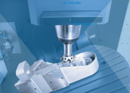
Our final plastic prototyping method is CNC machining. In this process, fabricators use a digital milling machine. This plastic prototyping method is ideal for producing one-off units for functional testing.
With the right mold material, you can come as close as possible to the final product with your prototype. There’s a wide choice of materials available.
As the material cools and the molecular bonds re-link the resin into its rigid form, these stresses are in effect locked into the part. Part stresses can cause warpage, sink marks, cracking, premature failure, and other problems.
Furthermore, fabricators can create highly realistic prototype finishes. Despite the use of resin, the resulting plastic prototype will have functionality and surface quality that compares to the real product.
Prototyping is a vital part of product development. For instance, you may have a product that you want to take from concept to final build.
Sink Marks Refers to areas of the molded part where it seems to be sunk in, due to un-uniformed wall sections, thick wall sections and rib/boss to thickness ratios being off
Keep these factors in mind when designing your injection molded part, and remember that it is easier to avoid problems in the beginning than change your design down the line.
The resulting plastic prototype will have mechanical properties that are close to an injected part. However, this outcome varies depending on the desired functionality and appearance of your project.
Shear Refers to when plastic enters into the mold and the melt is maintained by friction produced by speed and pressure. Too much shear can cause the plastic material to burn, too little can cause the material to freeze off causing short shot
Designing plastic parts is a complex task involving many factors that address application requirements. "How will the part be used?" "How does it fit with other parts in the assembly?" "What loads will it experience in use?" In addition to functional and structural issues, processing issues play a large role in the design of an injection molded plastic part. How the molten plastic enters, fills, and cools within the cavity to form the part largely drives what form the features in that part must take. Adhering to some basic rules of injection molded part design will result in a part that, in addition to being easier to manufacture and assemble, will typically be much stronger in service. Dividing a part into basic groups will help you to build your part in a logical manner while minimizing molding problems. As a part is developed, always keep in mind how the part is molded and what you can do to minimize stress.
Again, machine prototyping is possible using a wide range of materials. Accordingly, it’s a bit easier to find the right material for your project when using this method.
With Prototech Asia, you can rest assured that experts are always handling your projects. What’s more, we’re passionate about our work. Also, we have an extensive network of partners across multiple industries, so we can provide you with the best possible solution for your needs.
Gate Refers to where the plastic enters into the cavity of the mold. The two types of gates are as follows: 1. Automatically Trimmed Gates: Gates that incorporate features in the tool to break or shear the gate as the molding tool is opened to eject the part 2. Manually Trimmed Gates: Gates that require an operator to separate parts from runners during a secondary operation
The sub gate is the only automatically trimmed gate in this list. Ejector pins are necessary for automatic trimming of this gate. Sub gates are quite common and have several variations such as banana gate, tunnel gate, and smiley gate to name a few. The sub gate allows you to gate away from the parting line, giving more flexibility to place the gate at an optimum location on the part. This gate leaves a pin sized scar on the part.
SLA plastic prototypes have a smooth finish. This method works well for smaller parts to parts as big as 2 m in size. No matter the size of your product, you’ll still enjoy the same high-quality results with SLA plastic prototyping.
Using the resulting prototype, you can collect reliable information. For example, your injection molded prototype might give you insights into the mechanical operation of your product.
One way to avoid sink marks is to core out the solid sections of the part to reduce thick areas. If the strength of a solid part is required, try using cross hatched rib patterns inside the cored out area to increase strength and avoid sink. As a rule-of-thumb, make sure that all bosses and locating/support ribs are no more than 60% of the thickness of the nominal wall. Textures can also be used to hide minor sink marks.
You can accomplish this task by creating or requisitioning a computer-aided design (CAD) model. A CAD model is a digital mockup of your idea. It will show you and the specialist who will create your prototype what your product should look like.
Watch the recorded webinar to hear how Bastech delivers benchmarking results that prove the advantages of conformal cooling with significant improvements in cost, productivity and quality.
Vestige Material protruding from the gate area after gate runner has been removed from the injection molded part. This vestige is usually trimmed by the molding machine operator
While some stresses in an injection molded part are to be expected, you should design your parts with as much consideration for stress reduction as possible. Some ways to do this are by adding smooth transitions between features and using rounds and fillets in possible high stress areas.
The fabricator will begin the process by performing a complete analysis of your product. They’ll then design a tooling plan for your mold. Once the mold is ready, they can move on to creating your prototype.
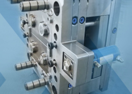
Injection molding machines, also known as presses, consist of a material hopper, an injection ram or screw-type plunger, and a heating unit. Molds are clamped to the platen of the molding machine, where plastic is injected into the mold through the sprue orifice. Presses are rated by tonnage, which is the calculation of the amount of clamping force that the machine can exert. This force keeps the mold closed during the injection molding process. Tonnage can vary from less than 5 tons to 6,000 tons, although higher tonnage presses are rarely used. The total clamp force needed is determined by the projected area of the custom part being molded. This projected area is multiplied by a clamp force of 2 to 8 tons for each square inch of the projected areas. As a rule of thumb, 4 or 5 tons/inch can be used for most products. If the plastic material is very stiff, it will require more injection pressure to fill the mold, thus more clamp tonnage is needed to hold the mold closed. The required force can also be determined by the material used and the size of the part, with larger plastic parts requiring higher clamping force.
Core Outs Refers to the portion of a part that is gutted out in order to achieve uniform wall thickness. This portion of the part has no end use function other than lightening the part and reducing warp
GETTING A QUOTE WITH LK-MOULD IS FREE AND SIMPLE.
FIND MORE OF OUR SERVICES:

Plastic Molding
Rapid Prototyping
Pressure Die Casting
Parts Assembly
