
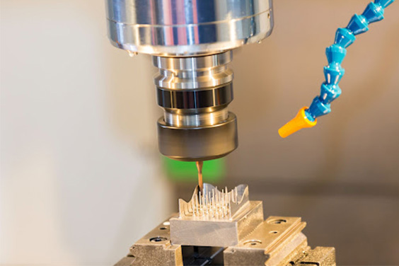
INJECTION MOULDING
Injection moulding parts and injection tools. Full solutions from design to production.
Plastic manufacturing in Canada - multi mold plastics inc
Author:gly Date: 2024-10-15
Access a wide breadth of capabilities through our highly vetted network.
The selection of the injection mold gate design depends on a number of factors, such as the volume of production, budget, time restraints etc. Mold plates are used to support molds and tools. They are made of metals such as aluminium and steel. The mold types can be classified into two-plate mold and three plate mold. Let us know more about both of them.
So, whenever possible, design your parts in a way that makes injection molding easy and inexpensive. Sometimes, however, you just can’t avoid complex geometries, but design for manufacturing (DFM) experts can help you find the right solution.
Compared to the two plate mold, the three plate mold has an additional plate that is found floating on the moving and fixed plates. The fixed plate and the center plate have a feed system in between to form injection molding products. The closing of the molding machine is usually achieved by the closing action that picks up progressively and closes the sections as they move forward.
There’s a way to address this, however. As the snap-fit on the right shows, it’s possible to remove some material from the case without adversely affecting the design. This makes it possible to mold the snap-fit using a simpler and less expensive tool for easier part release.
Our trained employees ensure your parts will be delivered on time and to spec.
What if you want to minimize your tooling costs? With a 250-part initial run, urethane casting is a great choice — it still uses tooling, but the molds are made of non-metal materials that cost significantly less. Typically, urethane casting is used for runs of parts in the 20 to 500-piece range.
The selection of the molding product type depends on several factors like components design, budget, and production volume. One of the significant questions that remain in the manufacturer’s mind during new product development is what type of mold is required?
Instead of trying to mold the entire head of the club as a single piece, you section it into three separate pieces: face, bottom and shaft, and top of the shell. After these three pieces are injection molded, they can be ultrasonically welded together. This secondary process adds costs, but those costs are a lot less than what you’d pay for complex tooling. Also, because sectioning is such a drastic design change, you’ll need new 3D-printed prototypes to test your three-part geometry and ensure there’s enough clearance between the parts to assemble them. For best results, use a 3D-printed material that’s as close as possible to your future injection molding material, especially in terms of tolerances and surface finish.
ACIS®, Autodesk Inventor®, CATIA® V5,Creo™ Parametric, IGES, Parasolid®, Pro/ENGINEER®,Siemens PLM Software’s NX™, SolidEdge®, SolidWorks®, STEP
This type of plate has three main plates or parts that are separated from each other at the opening. Pin-point gate is one of the significant advantages of this type of mold and it can be used for making multi-impression molds.
By signing up, you agree to our Terms of Use and Privacy Policy. We may use the info you submit to contact you and use data from third parties to personalize your experience.
The structure of the two plate mold is divided into two parts. As discussed above, one part is fixed, whereas the other is moving. The cavity side of the mold design remains fixed, and the core side moves.
There’s an exception to this rule — if the corner is on the parting line, then you can keep that corner sharp since it’s formed by the two halves of the mold.
By signing up, you agree to our Terms of Use and Privacy Policy. We may use the info you submit to contact you and use data from third parties to personalize your experience.
Steve Melito & Team Fictiv
The snap-fit on the left is problematic because it won’t support the use of a simple (and less expensive) mold. That’s because the underside of the snap fit isn’t accessible. In other words, the lower section of the plastic case gets in the way.
By signing up, you agree to our Terms of Use and Privacy Policy. We may use the info you submit to contact you and use data from third parties to personalize your experience.
In the fixed mold, there is a runner, which is placed on the parting surface. Once the molding process is completed, the runner and the injection-molded product stay in the moving part of the mold. The runner and the injection part are later removed from the parting surface.
We exist to eliminate bottlenecks in new product development by integrating the people, processes, and platform you need to source custom parts.
Red solo cups are a simple design, but what if you want to create a coffee cup? What do you do about the handle? The two halves of the injection mold can’t come together in a straight parting line. One solution is to incorporate slides, a type of action, for part removal. Yet this adds complexity and costs.
By signing up, you agree to our Terms of Use and Privacy Policy. We may use the info you submit to contact you and use data from third parties to personalize your experience.
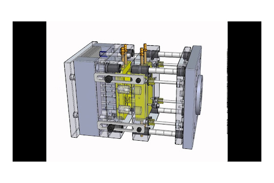
A three-plate mold consists of two parting planes and its mold splits into three sections. For a three-plate plastic molding design, the runner is present on the second parting plane that runs parallel to the main parting plane. The second parting plane allows the sprue and runners to get expelled when the mold is open.
How can you tell if your part design has undercuts in the first place? Imagine your part atop a glass table. One light shines on your part from above and another light shines on your part from below. If light hits every surface of the part, then there aren’t any undercuts. If some of the part is shadowed, however, then those shadowed areas are undercuts.
Create high quality custom mechanicals with precision and accuracy.
We exist to eliminate bottlenecks in new product development by integrating the people, processes, and platform you need to source custom parts.
The tool in injection molding, the injection mold, has two main parts: the core and the cavity. The parting line is where the two parts meet, and the direction of their movement is called the mold pull. In the image below, the line on the side of the toy soldier shows where the two halves of the mold came together.
Injected molded parts with recessed features called undercuts are more difficult to eject from the tool. This adds costs and complexity to your project, and undercuts that are too deep may be especially hard to remove. Yet, some product designs need undercuts for a fastening point or locating edge, which are essential to the design and can’t be removed.
Are you ready to scale up from 3D printing to injection molding? Then it’s time to tailor your part design for a process that uses metal tooling and has its own unique design requirements. This article begins with some injection molding basics and then explains how to optimize your part design to reduce tooling costs and avoid defects. You’ll also learn what to do if your part has an especially complex geometry, and there’s even a section about urethane casting — in case you’re not quite ready for plastic injection molding.
During the injection molding process, molten plastic (the charge) enters a nozzle and then passes through a sprue and runner system. This molten plastic then enters the mold through openings called gates. After the plastic cools, the molded part is ejected from the tool, typically with ejector pins.
Accelerate development with instant quotes, expert DFM, and automated production updates.
Along with undercuts, there are certain geometries that complicate the release of injection molded parts. For example, straight sides that are in the same direction as the mold pull are difficult to eject. The solution is to add a slight draft angle to the part’s sides — note that parts with long straight sides need larger draft angles. This taper is barely noticeable, but a few degrees make big a difference when ejecting parts.
Two plate molds are the most frequently used in plastic injection molding service. They include a parting plane where the mold divides into two halves. In a mold that has multiple cavities, the gate and the runner must be located in the parting planes to ensure that ejection takes place when the mold divides into two.
Two plate mold design is one of the simplest injection mold structures that has several advantages. Two plate molds consist of two main parts – side A and side B. When there is a load on the injection machine for injection molding products, side A is held still and fixed while side B remains movable. Here are some of the parts in the two plate mold design:
Fictiv provides engineers with a faster, easier way to order high-quality injection molded parts. When it’s time to scale up from low-volume 3D printing to high-volume injection molding, you’re bound to have questions about design and manufacturing. Our molding and printing experts have the knowledge and skill to help you optimize your designs and make the transition smoothly, so don’t go it alone. Create your free Fictiv account, upload your part drawing, and let us help you make the move to injection molding!
Three plate injection mold design engineering consists of two parting planes, and the mold divides into three parts. Thus, runners and components can be located on different parting planes. In three plate injection mold, the runners are generally ejected separately to the molded part. Therefore there is a probability of automatic degating. We hope that by now you are aware of the key differences in between the two types of mold. Hence, choose one that is best suited to your project requirements.
With 3D printing, you can produce the entire head as a single piece. With injection molding, however, it doesn’t make practical sense to try. Why? It’s because you’d need a mold with many different types of actions, and that would add significant expense to your project. In other words, design for manufacturability (DFM) suggests taking a different approach, called sectioning.
No matter what plastic production method is best for your project, Fictiv can help you every step of the way. We offer 3D printing, injection molding, and urethane casting (plus CNC machining) and provide design for manufacturing (DFM) assistance along with your quote. Keep reading to learn about scaling up from 3D-printed prototypes to injection mold-ready designs. Then create a free Fictiv account to get started on your manufacturing journey. We make complex parts at ridiculous speeds!
Many injection molded parts have commercial tolerances and smooth surface finishes. With 3D printing, the closest you can get to these conditions is PolyJet technology, which can also approximate the strength and stiffness of injection-molded plastic parts. You may need to adjust and re-test your sectioned parts, but 3D printing readily supports prototyping revisions.
Snap fits are injection molded features that are often used in product assembly. Check out the two snap fits in the image below.
The thinner and thicker areas of an injection molded part cool at different rates. Thinner areas cool and harden first, and thicker areas take longer. If there’s a significant difference in wall thickness, sink marks can occur. These injection molding defects happen when the center of a thicker section that’s still cooling pulls down the surface of a thinner section that’s already cooled and creates an unappealing surface divot.
By signing up, you agree to our Terms of Use and Privacy Policy. We may use the info you submit to contact you and use data from third parties to personalize your experience.
To gain more control on the desired mold opening sequence, it is also required to set the movement accurately. The closing of the mold is obtained by the closing action of the molding machine.
Two plate molds consist of a single parting plane from where the mold splits. In the case of a multi-cavity two-plate mold, the gate and runner is present in the parting plane. They make sure that the gate and the runner eject while the mold splits.
As the mold of the three plates opens up, the A and B halves are held together with releasable plate locks. The sprue is then released, and then the gate breaks away from that part. Under-cut pins hold the sprue back in another floating plate. When the tooling of the A-side is hit, a set of stop bolts. These two events occur successively.
Two plate mold is one of the most reliable and simplest mold designs. It has very few moving parts making it more straightforward to run in the production of injection mold slide design. Owing to its simple and straightforward design, it is cheaper than its counterparts.
When using three-plate advanced prototype molding for round parts, you need to ensure that the part is evenly filled. It is critical to make sure that the spaced gates are placed evenly around that particular part and have been evenly filled all around.

By signing up, you agree to our Terms of Use and Privacy Policy. We may use the info you submit to contact you and use data from third parties to personalize your experience.
By signing up, you agree to our Terms of Use and Privacy Policy. We may use the info you submit to contact you and use data from third parties to personalize your experience.
By signing up, you agree to our Terms of Use and Privacy Policy. We may use the info you submit to contact you and use data from third parties to personalize your experience.
Injection molds vary in size and complexity, so let’s start with a small but simple example: a red solo cup. Half of the mold forms the cup’s interior and the other half forms the cup’s exterior. Inside the tool, there’s a cone of plastic that protrudes from one side of the mold into the other.
The application of three plate mold requires the runner system to be positioned among different planes to automatic degating and injection location. The stripper plate is one of the significant differences between the two plate mold and the three plate mold used for plastic molding products. The significant difference also lies in the structure, orientation, and guide pin location. The three plate mold exists mainly to respond to the appearance and the production requirements. The injection pressure on the three-plate mold is not higher than the two-plate mold when a complete filling situation is concerned.
Then the A and B halves of the part get separated, and the pins get pulled from the Sprue, enabling it to drop from the mold. The part can get ejected off after the mold gets completely opened, just like normal two-plate plastic injection products.
When you’re designing a part for injection molding, try to visualize which surfaces will be made by the top of the mold and which surfaces will be made by the bottom. Then determine where the two halves of the mold will meet. It takes some practice and DFM assistance to do this, but it’s worth the effort.
By signing up, you agree to our Terms of Use and Privacy Policy. We may use the info you submit to contact you and use data from third parties to personalize your experience.
Like straight sides, sharp corners also get stuck in the mold during part release. The solution is to use rounded corners or fillets instead of sharp angles.
Now, let’s say you’re planning an initial production run of 250 parts. Low-volume injection molding can produce a few hundred up to tens of thousands of parts. Plus, low-volume molds can be cost-effective — Fictiv offers low-volume molds made from aluminum, and soft and semi-hardened steels.
The general construction of the three plate mold is built about the opening sequence of the molding product. Understanding the complete design of the mold is required to know how the mold functions. The mold opens in three different stages.
The three plate mold has three cavities that are filled through a centrally located pinpoint gate. The mold is typically divided into three sections:


LK-Mould Ltd.,
No.15, JinShen Road, Jin xia District
Changan Town, Dongguan
523850 Guangdong
China

