
INJECTION MOULDING
Injection moulding parts and injection tools. Full solutions from design to production.
Overmold Process in Injection Molding - overmolding injection molding
Author:gly Date: 2024-10-15
The burr is a defect that occurs when part of the molten polymer flows through the existing gaps in the injection mould such as parting plane, aeration zones, ejectors, etc. Burring occurs for the following reasons:
We also help in establishing an entire assembly along with testing procedures. All the procedures that are established are optimized to deliver the best, in terms of quality and an efficient turnaround time.
Trapped air will result in voids and bubbles within the moulded plastic part, incomplete filling or surface defects such as stains or burn marks.
This also ensures better lead time and enables us to incorporate any type of minor or easy modification that the mold may require.
We ensure to only use imported and certified steel as well as the standard components you prefer to build your molds. This guarantees us to manufacture medical device molds of the optimum quality that medical device manufacturers should adhere to.

A weld line (also called a weld mark) is formed when two melt flow fronts travelling in opposite directions meet. In contrast, a bond line occurs if these two fronts flow parallel to each other creating a bond line.
However, achieving uniform shrinkage is complicated by the presence and interaction of many factors such as the orientations of the polymer molecules, temperature variations in the mould walls, compaction variations in the plastic parts (over-compacted areas and under-compacted areas, due to unbalanced flow paths), etc. Note that areas of higher compaction, such as injection gates, have a lower shrinkage since part of the compaction of the molten polymer compensates for it. In contrast, areas further away from the gate are subject to less compaction and therefore tend to have a higher shrinkage.
VEM Tooling also ensures to deliver spare parts and the replacement parts of the medical device molds at the lowest lead time. Additionally we can guarantee the quality of the replacement or the spare parts is as per the quality standard.
The jetting defect occurs when molten polymer is pushed at speed through a small area, such as the injection nozzle or gate, to access a much larger area. The jetting defect results in mechanical weakness in the part, surface imperfections and multiple internal defects.
The formation of wrinkles or waves is due to the fact that a part of the flow front cools rapidly on the mould walls producing a fold on the flow front itself. Themain factors influencing the formation of these wrinkles are the flow velocity, the temperature of the mould walls, and the temperature of the molten polymer, among others.
Traditionally, the joint angle between the two faces is used to differentiate weld lines from joint lines. A joint angle of less than 135º produces a weld line, while a joint angle of more than 135º is defined as a joint line. In general, a weld line mark disappears when the joint angle reaches between 120º and 150º. The weld lines are considered more critical than joint lines in terms of both aesthetics and mechanical properties of the joint. Translated with www.DeepL.com/Translator (free version)
Medical device manufacturing requires that every device and equipment is manufactured according to the standardized quality and without any compromise to the safety. Thus, Medical Device Injection Molding should always be carried out in ISO certified cleanrooms or whiterooms. This ensures that medical devices are protected from all types of dust, aerosol particles, airborne microbes and chemical vapors or any other contaminants at every development stage.
A poor finish can be caused by the formation of wrinkles or waves at the edges of the part or in the last filling areas during injection moulding.
Standardization and quality are part of our companies core values. We deliver the best possible experience and product to our customers, every single time consistent. Take a look at our certificates!
The Class 10,000 Clean Room includes injection machines for medical devices, assembly and subassembly units and machines as well as final packaging facilities. The cleanroom is equipped with the latest technology such as QC equipment and robots to ensure smooth mass production capacity. Along with the production facility, we also develop validation protocols, testing procedures and process improvement studies to ensure highest quality and competitiveness.
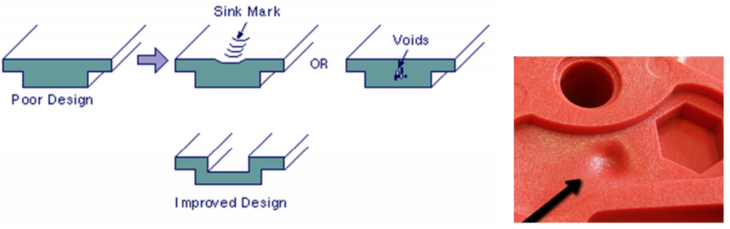
Sinkage marks are depressions in the surface of the plastic injection moulded part caused in the last phase or stage of the plastic injection moulding process, during the cooling process. The thicker sections of the plastic cool at a slower rate than the others, resulting in a higher percentage of shrinkage in that local area. After the material on the outside has cooled and solidified, the material on the inside begins to cool and its shrinkage pulls the surface inwards, causing a surface depression.
VEM Tooling’s Thailand Plant is ISO 13485 certified and has an ISO 7/Class 10,000 cleanroom after ISO 14644-1:2015 certification. Our mold design, engineering and manufacturing team follows rigorous standards to make medical device molds.
Incomplete filling occurs when a one injection moulded part is missing material to correctly generate its geometry. This occurs when the molten polymer cannot fill the entire cavity (or cavities) in the Injection mould, usually the thinner sections where the polymer melt cools before completely filling the mould. Any factor that increases the flow front resistance of the polymer melt can result in incomplete filling. Some of these factors are:
We support medical device companies with an end to end solution by carrying out their entire supply chain. This ranges from improving product design for manufacturing purposes & engineering to molding, product assembly, and its packaging.
At VEM Tooling, we focus on providing precision, accuracy and quality for our medical device manufacturers. We are one of the few medical device injection molding companies that provides the entire supply chain with manufacturing capacity in cleanrooms and whiterooms.
VEM Tooling is committed to providing our clients with the best medical device manufacturing service. At VEM, we also ensure that you receive clear and timely communication. These are the core values at VEM.
To better understand how VEM Group serves the medical device manufacturing industry contact us or request a quote today. We are looking forward to becoming your trusted medical device injection molding partner.
The locations of the air leakage areas in the moulds are located in the areas that are filled at the end of the injection cycle or phase. A common cause of the trapped air defect is an insufficient size of the mould vents. Another common cause is when racetracking occurs (tendency of the polymer melt to flow preferentially in thicker sections leaving thinner areas with trapped air). Translated with www.DeepL.com/Translator (free version)
VEM Tooling continually invests into engineering resources thus, we have the expertise, skill-set and technical knowledge to assist you with your medical device manufacturing across various stages and complexity levels.
The warping or twisting of an injection-moulded plastic part is therefore due to the existence of a series of residual internal stresses in the part which are in turn generated by the differential shrinkage of the material during cooling. If the shrinkage throughout the part is uniform, the resulting part does not warp or twist, it simply shrinks uniformly and becomes smaller. Thecrystalline polymers, e.g. acetal, nylon, high density polyethylene, polyethylene terephthalate and polypropylenecause the most serious problems with shrinkage from 1 to 4%. Amorphous polymers, e.g. polystyrene, acrylic and polycarbonate are more treatable, with shrinkages of only 0.3 to 0.7%.
A rule of thumb to avoid excessive distortions in the part due to temperature differences after injection, is that the average temperature differences in any part of the part after injection should not be greater than 15-20ºC.
All the equipment in the clean room at VEM is equipped to be highly automated with robotics. This aids our engineering and manufacturing team to reduce production errors. It also optimizes the manufacturing cycle thus, boosting productivity.
The trapped air defect appears when a certain amount of air cannot escape out of the mould during injection, a small area without material appeared in the injected part. In a correct Injection mould design, at each injection, air is exhausted through mould vents, mould inserts or even ejectors, which also act as vents.
The following recommendations can be used to reduce the impact of weld lines and parting lines on injection moulded parts.
You will experience fast and direct communication which ultimately leads to a seamless and smooth manufacturing process.
Delivering all facets of medical device manufacturing from medical device plastic injection molding to assembly and packaging in a Class 10,000/ISO7 Clean room environment.
Some of the practices we develop in the Moldblade Engineering Department to correct the problem of incomplete filling are:
Weld lines and joint lines can be caused by holes or insertions in the part, the existence of multiple injection gates, or due to areas of varying wall thickness where hesitation or race-tracking occurs.
The dimensional shrinkage of parts is inherent to the injection moulding process. Shrinkage occurs because the density of the polymer varies from processing temperature to ambient temperature (see, for example, the specific volume of a semi-crystalline polymer in Figure 5.46 – PVT curve). During the stages of the injection moulding process, cooling shrinkage produces a series of internal stresses in the part. These residual stresses act on the part with similar effects as possible externally applied stresses. If the residual stresses induced during moulding are high enough, the part after ejection from the mould may warp / twist or warp, resulting in defective parts.
At VEM Tooling, we build medical device molds in our factory units due to which we have complete control over quality. To design and build the mold, we either follow customer standards or use our VEM standard design.
– Reduce the injection speed. High plastic injection speeds can cause jetting, which causes trapped air to appear right at the inlet gate. Reducing the injection speed will give the displaced air at the gate enough time to escape through the aeration zones.
Occasionally, the use of high compaction pressures causes acceptable sink marks by reducing volumetric shrinkage although these cannot be completely eliminated. This is because the volumetric change of plastic from melt to solid is about 25% and the compressibility of plastics at typical injection moulding pressure is only 15%, which means that it is impossible to compact the molten plastic sufficiently to compensate for cooling shrinkage.
Throughout the process, we follow standard protocols and keep continuous improvement efforts to the highest level. This allows us to remain highly competitive in terms of quality and lead time.
VEM’s Medical & Healthcare Tooling Factory encompasses an extensive industry experience in the medical device manufacturing industry. We understand the manufacturing standards that need to be followed which is why we ensure to adhere to the ISO 13485 production standards.
Our manufacturing experience and input during an early product design phase has helped our clients to save upon resources and time. By partnering early during the product design phase development, we have eliminated common errors and mitigated redesign issues that may arise due to complexities thus, we encourage medical device manufacturers to partner with us during the product design phase stage.
If welding or joining lines cannot be avoided, a good practice is to ensure that they are generated in low visibility or mechanically non-critical areas. This is often done by modifying the plastic injection gate, modifying the flow fronts and the areas where the weld/joint lines occur. Another practice is to try to achieve a good joint between the two fluxes so that the mechanical weakness that occurs is not excessive. To do this, the aim is for the junction of the two flux fronts to take place at the highest possible temperature and pressure, so that they are not far from the inlet port. Translated with www.DeepL.com/Translator (free version)
Some of the actions to be taken to improve the surface finish are related to actions to increase the flow rate and temperature of the molten polymer and the mould walls. Therefore, the improvement of the surface quality is achieved by measures such as:


LK-Mould Ltd.,
No.15, JinShen Road, Jin xia District
Changan Town, Dongguan
523850 Guangdong
China

