
INJECTION MOULDING
Injection moulding parts and injection tools. Full solutions from design to production.
Messenger Molding - Plastic Injection Molding Company - plastic injection moldin
Author:gly Date: 2024-10-15
Through UnitedHealthcare, UMR creates and publishes the Machine-Readable Files on behalf of Crescent Industries, Inc. To link to the Machine-Readable Files, please click on the URL provided: https://transparency-in-coverage.uhc.com/
Our helpful design aid demonstrates part features that are too thin or too thick, bad bosses, right and wrong ribs, and other considerations to be mindful of while designing parts for injection molding.
Let's begin by coring out your thick part, which will still retain the overall height and diameter of your part without necessarily sacrificing performance. There's a good chance you'll increase the part's performance and cosmetic appearance, too.
Tough Black (Loctite Henkel 3843) and Ceramic-Filled (BASF 3280) are two new advanced photopolymer materials now available for 3D printing.
You can minimize all of these concerns through a core-cavity approach. This design technique requires the outside and inside walls to be drafted so they are parallel to one another. This method keeps a consistent wall thickness, maintains the part integrity, improves the strength and moldability, and decreases the overall manufacturing cost.
Proto Labs, Inc. 5540 Pioneer Creek Dr. Maple Plain, MN 55359 United States P: 877-479-3680 F: 763-479-2679 E: [email protected]
Our digital factories create prototypes and low-volume parts fast, while our manufacturing network, offers advanced capabilities and volume pricing.
Next, we'll focus on the design of the support ribs. The ideal way to design ribs is by using a rib-to-wall thickness ratio of 40 to 60 percent the thickness of adjacent surfaces. The main body of the part should be designed thick enough so any adjacent rib extruded from it is about half of the thickness. This helps you avoid thick sections that may cool at different rates than the thin sections. It also helps in reducing sink and stresses that can create warp in your part.
Hot tip gates work well as they have minimal part waste from sprue and runner systems. A hot tip is best for parts that require a balanced fill from the center to the outside edges. This minimizes any mold shift as tab gates can create an unbalanced pressure in a mold. Hot tip gates are often the most cosmetically appealing gate (about 0.050 in. diameter) and often times can be hidden in a dimple or around a logo or text.
Radii on the other hand isn't a necessity for injection molding, but should be applied to your part for a few reasons—eliminating sharp corners on your part will improve material flow as well as part integrity.

We've learned from experience that, before production begins, there are important design elements to consider. These may improve the moldability of the parts, and ultimately, may reduce the chance of production hiccups, cosmetic defects and other issues.
Get machined parts anodized and chromate plated with our quick-turn finishing option. Eligible materials include aluminum 6061/6082 and 7075.
Controlling wall thickness during part design helps manage cosmetics, weight and strength of your part. Parts that are too thick result in unsightly sink, warp and internal voids (pockets of air). To avoid this, materials have recommended wall thickness guidelines—remember this is only a general rule as not all parts may have wall thicknesses at the high and low ends indicated on the chart.
Applying draft and radii to a part is vital to a properly designed injection-molded part. Draft helps a part release from a mold with less drag on the part's surface since the material shrinks onto the mold core. Limited draft requires an excessive amount of pressure on the ejection system that may damage parts and possibly the mold.
This guide walks you through everything from quoting, design analysis, and shipment to best practices that ensure your model is optimized for molding.
Collaborates, communicates and coordinates critical tasks and deadlines to ensure your new injection mold tooling is built on time.
External undercuts are the easiest and most cost effective as we accommodate through pin-actuated side-actions. These side-actions move in tandem with the mold when it is opened and closed while the cam rides along an angled pin. When opened, the cam is fully retracted so the part can be easily ejected without mold damage and closes again till the cam is in position to create the next part.
Direct sprue gates are the least appealing and are used with specific materials that have a high glass content or where the middle of the part requires secondary machining. Direct sprue gates have a large diameter that is difficult to manually remove and often times require a fixture that is removed by milling.
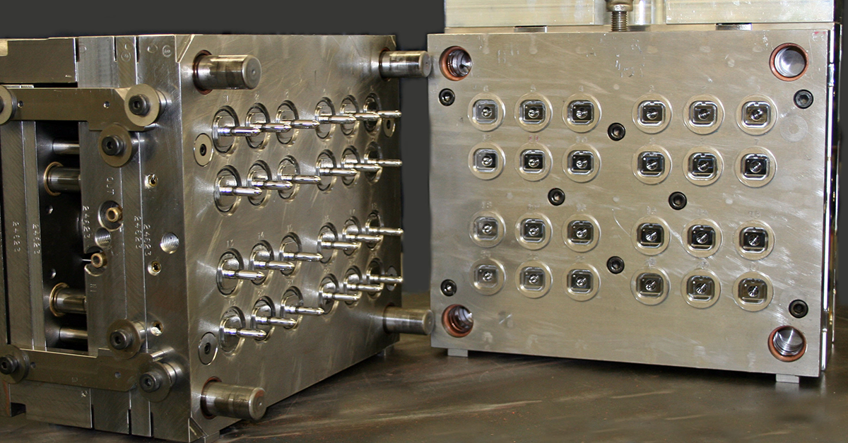
Gating and ejector pins are a necessity for plastic resin to strategically enter the mold and plastic parts to effectively be ejected from the mold. We've learned from experience that there are several ways to gate or eject your part, and the locations should be considered before you are ready to proceed with tooling.
The resin filling the mold cavity flows better around soft corners much like the flow of a river. Rivers don't have 90 degree corners as the water flow creates inside and outside corners so it moves easily towards its final destination. Similarly, plastic resin wants to take a path of least resistance to minimize the amount of stress on the material and mold. Radii, like draft, also aid in part ejection as rounded corners reduce the chance that the part will stick in the mold causing it to warp or even break.
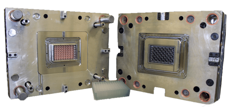
At Crescent Industries, we offer comprehensive plastic injection mold building capabilities to meet your diverse needs. Our expertise in this field allows us to rank among the top providers of plastic injection mold tooling and molding solutions.
A good rule of thumb is to apply 1 degree of draft per 1 inch of cavity depth, but that still may not be sufficient depending on the material selected and the mold's capabilities. Protolabs uses CNC milling to manufacture the majority of the features in the mold. The result of our manufacturing process drives a unique wall thickness and draft angle based on the end mill that we are using for each feature. This is where our design for manufacturability (DFM) analysis becomes particularly helpful as our software looks at each part feature separately and compares it to our toolset. The design analysis highlights the part geometry where increased draft and thickness may be required.
Let's say you're designing a simple box. When draft is applied to the outside and inside surfaces in the same mold half, you create a very deep rib that is difficult to manufacture and increases tooling costs. It also increases the chance of mold damage due to difficult ejection and short shots due to lack of mold venting in the deep rib.
Along with employing proper wall thickness, additional considerations should be looked at to ensure a part's design integrity remains intact. One may assume that the thicker the part, the stronger the part—this is a false assumption. A properly designed part that is intended to be structural should contain ribs and supporting gussets, which increase strength and can help eliminate cosmetic defects like warp, sink, and voids.
The core and cavity are often referenced as the A and B sides or top and bottom halves of a mold. A core-cavity approach to part design can save manufacturing time and money and improve the overall part cosmetics.
In cases that are not adaptable for side-actions, we can use manually removed inserts. These are mold components that are greater than a half-inch cube and are loaded by an operator into the press before it closes. After the part has been molded, the part is ejected along with the insert. The operator then takes the part and manually removes the insert and places it back into the mold for the next part.
Our experienced team of engineers and mold designers collaborates closely with you and your specific product requirements, part geometry, and production volume to build new injection mold tooling that produces a quality product
Tab gates are most commonly used as they offer a mold technician the optimal processing capabilities and have the ability to be increased in size if the process requires it. A tab gate is tapered down in size from the runner, so the smallest point is at the part's surface. This allows a freeze point between the part and runner removing the heat from the surface of the part. You want the heat removed from this surface to minimize any risk of sink in the part. After molding, the tab gate needs to be manually removed leaving a gate vestige within 0.005 in.
Parts arrive at injection molding in different ways. Some are first prototyped through 3D printing where moldability considerations are of limited concern. Others take a more traditional machining route that allows for iterative testing in engineering-grade materials similar to that of molding. And many simply jump right to injection molding.
Sub gates are generally used by incorporating a tunnel gate into the side of the part or into an ejector pin (post gate). Both gate styles generally can decrease the size of the vestige left on the exterior of the part. Tunnel gates still enter the part externally, but are mid-way down a parts surface, so they typically leave less of a gate vestige. Post gates leave no visible vestige on the exterior of the part as the part fills through one of the ejector pins close to the perimeter of the part. The risk is the cosmetic shadow left on the opposite side of the part due to heat and part thickness. So, be cautious when using this for highly cosmetic parts that have texture or a high polish.
With a solid grasp of the techniques to improve part moldability, it is much easier to move into low-volume, and eventually high-volume injection molding. The next step is to upload your 3D CAD model online where you'll receive an interactive quote with free DFM analysis within hours. As we said earlier, the DFM analysis will highlight any moldabilty issues and even suggest solutions. We recommend pairing that design feedback with a conversation with one of our experienced applications engineers who will help with any further guidance you might need before production begins. They can be reached at 877-479-3680 or [email protected].
Rapid injection molding requires that your part design should be as simple as possible, right? This is another false assumption as we support complex part designs that requires undercuts, through holes and other features.
Ramps and gussets are yet another design element to strengthen and cosmetically improve your part. Again, plastic prefers smooth transitions between geometries and a small ramp helps the material flow between levels. Gussets help supporting walls or features while reducing molding stresses.
Sharp corners have high-stress concentration and plastic flow is hindered. Rounded corners have reduced-stress concentrations and plastic flow is enhanced.
Discover the countless benefits of partnering with us for all your injection molding manufacturing needs and let us show you why we are the perfect match for your business.


LK-Mould Ltd.,
No.15, JinShen Road, Jin xia District
Changan Town, Dongguan
523850 Guangdong
China

