
INJECTION MOULDING
Injection moulding parts and injection tools. Full solutions from design to production.
Medical injection molding - medical device plastic molding
Author:gly Date: 2024-10-15
This requires two molds: one for the substrate and another for overmolding. The process is time-consuming and labor-intensive.
Since the same type of plastic can be overmolded, this offers great production flexibility. We can first produce a smaller part as a substrate, and do the over-molding to wrap the substrate, which can significantly increase the product’s wall thickness.
4. Improving Thermal Insulation: In some products, especially those that need to maintain or restrict temperature exchange, thicker walls are required for enhanced thermal insulation. This is commonly seen in products like thermal containers, housings for electronics, or components in heating and cooling systems, where the thickness of the wall plays a crucial role in insulating the product or component from external temperature variations.
1. Enhancing Structural Strength and Rigidity: In certain scenarios, the demand for increased structural strength and rigidity necessitates the use of thicker walls in injection molded parts. This is particularly important in applications where the parts are subject to high stress or load, requiring additional material to maintain integrity and functionality.
The below animation illustrates how the substrate is designed to be encapsulated within the overmold. This significantly enhances the strength in the load-bearing areas of the part.
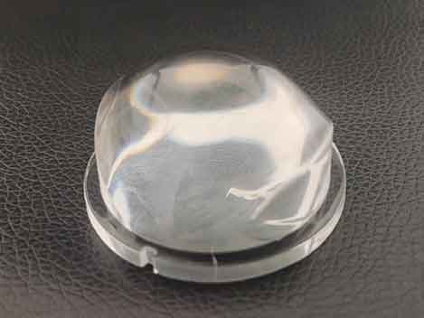
Some materials, like PC, are naturally suited for thick-walled products, such as lenses up to nearly 30mm thick. Despite this thickness, they don’t exhibit significant shrinkage deformation, maintaining optical performance.
In the world of injection molding, the common practice is to maintain thin and uniform wall thicknesses in products. However, there are scenarios where maximum wall thickness is necessary, pushing the boundaries beyond conventional limits. In this article, we delve into the methods of creating injection molded parts with thicker walls, along with the challenges and considerations that need to be addressed in the process.
With the electrification of automobiles and the introduction of advanced driver assistance systems (ADAS), the number of onboard electronics in vehicles is increasing, along with the sources of electromagnetic noise and heat.
2. Design Constraints with Close Proximity Features: There are situations where design elements such as bosses (raised features used for alignment or attachment) and walls are in very close proximity to each other. In such cases, it becomes impractical or impossible to hollow out these areas. The resulting design constraint leads to the necessity of having thicker walls to accommodate these closely spaced features while maintaining the part’s structural integrity.
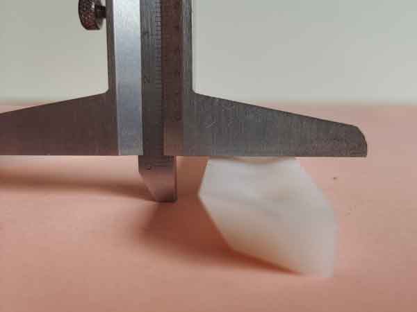
The white sample, made from standard PP (polypropylene), clearly exhibits substantial shrinkage, the concave in the middle is obvious. In such cases, even increasing packing pressure and time doesn’t mitigate this shrinkage.
In conclusion, while injection molding typically favors thin, uniform walls, certain applications necessitate thicker walls. Overcoming challenges like uneven cooling, increased internal stress, and potential defects requires advanced techniques such as enhancing machine performance, modifying materials, and employing overmolding. This article underscores that while producing thick-walled parts is complex, with careful planning and execution, it is possible to achieve quality and functionality in these specialized products.
While metal materials are excellent in electromagnetic wave shielding and heat release properties, they are heavy and difficult to fabricate, resulting in a growing need for alternative materials to metal for onboard electronics for vehicles, where weight reduction is essential.
Due to the risk of electromagnetic noise causing malfunctions and accidents with onboard electronics and automobiles, it is essential to take electromagnetic compatibility (EMC) measures such as preventing the emission of electromagnetic noise, ensuring resistance to the effects of electromagnetic noise, and ensuring proper operation even under the effects of electromagnetic noise.
Our injection molding with thermal conductive and EMC shielding is a high-performance thermoplastic resin molding product that protects electronics from problems by preventing thermal runaway and electromagnetic interference.
Additionally, increasing the number of overmolding layers (e.g., double or triple overmolding) can further thicken the walls, even producing solid plastic products. This is rare and costly, but it’s a possibility worth mentioning for informational purposes.
It can be said that using the overmolding approach is the most straightforward solution, as it is less constrained by the limitations of injection molding machines and the shortcomings of the modified materials mentioned above, though it does incur higher costs.
The images show that the product is free from noticeable bubbles and injection lines, achieving a satisfactory level of quality.
Thicker walls mean longer cooling times during the injection molding cycle. Cooling time is almost proportional to the square of the wall thickness, following a quadratic relationship (y =K* x^2). For example, with PA6 material at 8mm thickness, the total injection molding cycle is about 93 seconds, with cooling taking around 70 seconds. Thus, increasing wall thickness comes at the cost of higher production expenses.
3. Adding Material Mass and Inertia: For certain applications, increasing the mass and inertia of a part is desirable. This can be achieved by designing the part with thicker walls. The added mass can be beneficial in applications where extra weight is necessary for stability or momentum, such as in certain mechanical or automotive components.
Injection molding enables flexible shaping, and the resin is about 45% lighter than aluminum, contributing to heat release and EMC measures as well as weight reduction by replacing metals.
The maximum wall thickness limit in injection molding primarily ensures product quality, structural integrity, and production efficiency. These factors should be considered in the design phase, adhering to material and design guidelines to ensure the final product’s quality and performance.
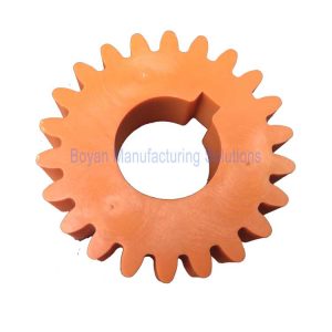
This is a plastic connector designed to withstand heavy loads, necessitating increased wall thickness. However, during a single injection molding process, a wall thickness of 8mm is the limit, as it already shows significant sink marks, and the molding time approaches 1 minute and 40 seconds. Yet, this 8mm thickness doesn’t meet the required strength criteria.
In this example, it’s evident that material modification significantly reduces shrinkage, allowing for the production of products with greater wall thickness.
Now, by adopting an overmolding approach, the wall thickness can be increased to over 15mm, with the product’s flatness largely meeting the requirements.
The main challenge is preventing defects like bubbles and injection lines and avoiding excessive internal stress after cooling.
Specialized injection molding machines and screws are required to ensure high injection speeds and uniform pressure and temperature to minimize internal stress.
Injection molded parts that are too thick can lead to a series of problems, hence the existence of maximum wall thickness limits. The main issues with overly thick injection molded parts include:
This is a headlight lens made of PC material with a thickness of around 34mm, produced using a specialized injection molding machine. Since the gate scar is concealed after assembly, it doesn’t require aesthetic treatment.
The primary limitation on part wall thickness is physical filling. Adding calcium carbonate or talc to plastics can reduce material shrinkage. These additives don’t shrink and can alter the structural state of some plastics. Glass fiber reinforcement changes the crystallinity of some plastics, significantly reducing their shrinkage rate. However, adding these components is complex, as they can alter material gloss, reduce strength, and increase brittleness. In some applications, like food-grade plastics, most additives are not permissible.
The cooling time in injection molding is influenced by many factors, making the calculation formula quite complex. The data in the above graph only roughly reflects the relationship between wall thickness and cooling time. However, it does show that cooling time increases almost proportionally to the square of the wall thickness, which significantly impacts injection molding costs.


LK-Mould Ltd.,
No.15, JinShen Road, Jin xia District
Changan Town, Dongguan
523850 Guangdong
China

