
INJECTION MOULDING
Injection moulding parts and injection tools. Full solutions from design to production.
How to Develop a Plastic Prototype? - prototype plastic
Author:gly Date: 2024-10-15
The polymer granules melt into fluid, which is then forced through a 2D die open tool. This pushes the materials into a hollow tube based on the die’s particular geometry. After chilling, the material solidifies into a tube shape. This item is now waiting to be cut into the desired sizes.
Tolerances: Molders can generally hold about ±0.003 in. machining accuracy. Shrink tolerance depends mainly on part design and resin choice. It varies from 0.002 in./in. for stable resins such as ABS and polycarbonate to 0.025 in./in. for unstable resins such as TPE. There are techniques for getting the most accuracy out of injection molding. Contact an applications engineer at your injection molder for more information.
Draft: Draft (slope the vertical walls) as much as possible to make it easier to eject parts without drag marks or ejector punch marks. Draft also lets designers make deeper features, plus it reduces tool chatter and cosmetic defects when milling deep walls. If you can fit it in, use 1 deg. of draft or more. On core-cavity designs, use 2 deg. or more. A rough rule of thumb is 1 deg. of draft for each of the first 2 in. of depth. From 2 to 4 in. of depth, either 3 deg. of draft or a minimum of 1/8 in. thickness may be required.
Steel Core Pins: These holes can be made with steel core pins in the mold. A steel pin is strong enough to handle the stress of ejection and is smooth enough to release cleanly from the part without draft. There shouldn’t be any cosmetic effect on the resulting part; if there is, it will be inside the hole where it won’t be seen.
If you have any questions regarding injection molding or rapid injection molding, please feel free to call a Protolabs application engineer at (877) 479-3680 or e-mail [email protected].
Stainless steel fibers are used to control EMI (electromagnetic interference) and RFI (radio frequency interference) typically in housings for electronic components. They are more conductive than carbon fiber.
When choosing a material for a part, relevant properties might include mechanical, physical, chemical resistance, heat, electrical, flammability, and UV resistance. Resin manufacturers, compounders, and independent resin search engines have data online. Here is a quick look at some common commodity and engineering resins.
From wall thickness and radii to ramps and ribs, here’s a quick look at factors designers and engineers should consider if parts will be injection molded.
Pickouts: A pickout is a separate piece of metal inserted into the mold to create an undercut. It is ejected with the part, then removed by the operator and re-inserted in the mold. Using a pickout lets designers overcome shape and positioning restrictions, but is more costly than sliding shutoffs or using a side-action.
Carbon fiber strengthens and/or stiffens a composite and aids in static dissipation. It has the same limitations as glass fibers. Carbon fiber can make plastic very stiff.
Selecting Colorants: Stock colors from the resin vendor are typically black and natural. Natural might be white, beige, amber, or another color. Semi-custom colors are created when colorant pellets are added to natural resins. For available colors, check with your injection molder. In some cases, such as at Protolabs, there is no added charge for our inventory colors. But they may not be an exact match and may create streaks or swirls in parts. Custom colors that need to match an exact Pantone or color chip need to be compounded with a resin supplier. This process is slower and more expensive, but produces a more accurate match.
The part on the left is the originally designed part. The part on the right has been cored out to reduce part thickness while still being able to perform all of its necessary functions.
Tab Gates: Thin edges restrict flow and can break during gate trimming. Tab gates give injection molders a thick area to place a gate into your part. There may be alternatives, so please contact the molder’s applications engineers.
Bumpoffs: A bumpoff is a small undercut in a part design that can be safely removed from a straight-pull mold without using side-actions. Bumpoffs can solve some simple slight undercuts, but are sensitive to geometry and material.
The completed result from the extrusion process has a two-dimensional shape that is continuous in length. Extrusion creates linear forms that may be cut to different lengths and/or notched, punched, or otherwise produced, frequently while the process is running.Extrusion and injection molding both have benefits. The capacity to generate complicated cross-sections is one advantage of employing the extrusion technique over other approaches. Furthermore, as compared to other techniques, both rigid and soft materials may be molded into any shape, and the final products have a flawless surface finish. There is little waste in both the injection molding and extrusion operations since the debris may be recycled again.
Because of the intricacy of the mold construction, injection molding generally has a higher initial design cost. Its cyclical manufacturing, on the other hand, usually results in a completed component that does not require additional assembly or secondary processing.
Wall Thickness: The most crucial design requirement for getting good molded parts is to maintain constant wall thickness. They minimize the potential for warped or distorted parts.
The bosses on the left are poor as they are too thick and might not fill completely, leaving voids. The bosses on the right, however, create strength without having sections that are too thick.
Designing plastic parts that can be molded has always been important for traditional injection molding processes, but it’s particularly beneficial for parts about to be rapid injection molded (RIM) to ensure speed and quality remain constant during manufacturing. Here’s a look at many of the critical design considerations encountered during rapid injection molding
Radii: Sharp corners weaken parts and create molded-in stress from resin flow. Designers should add radii in sharp corners.
RIM accommodates side-action and hand-load inserts, as well as simple overmolding and insert molding. Selective use of electrical discharge machining (EDM) can improve mold features such as corners and edges. And several surface finish options are available. All of this lets RIM make parts in a few weeks rather than the months needed for traditional injection molding methods.
The plastic resin is placed in the hopper, which causes the plastic out from the feed portion to be released into the compressing area, where friction heat is applied. A reciprocating screw pushes the plastic through a long chamber. Melting, or molten plastic, is pushed via the injector into a sealed, cooled/hot mold. The melt may be readily shaped into the mold’s desired form and size.
Long glass fibers are used like short glass fibers to strengthen and reduce creep, but make the resin much stronger and stiffer. The downside is that they can be particularly challenging to mold parts that have thin walls and/or long resin flows.
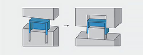
Undercuts: An undercut is an area of the part that shadows another area of the part, creating an interlock between the part and one or both mold halves. On the image below, the left image (1) illustrates a clip with an undercut feature. On the right image (2), an access hole beneath the undercut lets the mold protrude through the part and provides the needed latch shutoff geometry.
Injection molding and extrusion molding are two prominent plastic molding processes used throughout the industrial and manufacturing sectors to create items of various shapes and sizes. Both approaches offer distinct advantages based on the products and the consumer. Let’s look at the distinctions between injection molding and extrusion molding to help you decide which is ideal for your manufacturing needs.
Among industrial producers, injection molding and/or extrusion processes are defined to create items of various forms and sizes. The injection molding technique is built on the melted die-casting technology. The clamp and the injection unit comprise the injection-molding unit. Injection molding, as opposed to extrusion, produces three-dimensional structures.
Side-Actions: Side-actions form undercuts on the outside of a part. The undercuts must be on or connected to the parting line. They must also be in the plane of the parting line and connected and perpendicular to the direction the mold is opening.
Core Geometry: Core out parts to eliminate thick walls. You get the same functions in a well molded part. Unnecessary thickness can alter part dimensions, reduce strength, and necessitate post-process machining.
In terms of plastic extrusion, this method was first used to process rubber in 1836. This is a technique in which molten plastic or a variety of alternative materials are constantly forced into a two-dimensional die aperture by feed screws. The molten form is then passed through a succession of templates or blocks, where it preserves the correct shape as it cools.
With RIM, CAD models are sent directly to the production floor where mold milling begins. In most cases, molds are fabricated from aluminum, not steel. This allows for faster and more cost-effective tooling compared to traditional steel molds.
When a range of lengths of the same profile shape is required, extrusion is appropriate. Setup and design expenses for comparable products are minimized by creating a stock product with a continual production chain and cutting to length post-process per order.
The choice between plastic extrusion and injection molding does not have to be a contest. Both of these technologies serve distinct functions and have distinct advantages, and both are beneficial to plastic producers. Extrusion cannot generate the intricate 3D forms that injection molding can, nor can injection molding produce the unusual cross-sections that extrusion can. Each technique has a distinct position in the plastic production process.With that knowledge, we believe you’re well off on your journey to understanding the plastic molding process and can choose a molding form or manufacturer wisely. If not, do remember to read again, for valuable insights into the issue.
This is among the most used ways of molding polymers into 3D forms. It is founded on the molten die casting process and comprises a clamping unit and an injection unit.
Plastic molding is generally accomplished through two processes used by plastic producers. Plastic injection molding is the first method, in which producers “inject” molten polymer material into a mold and allow it to settle and cool into a specified form. Manufacturers push molten plastic through a die to generate the required form in the second process, plastic extrusion.
Extrusion is capable of producing complicated cross-sections, including such multi-lumen tubing used in medical equipment or food processing. Extruded materials have flat surfaces that do not necessitate post-production “clean-up.”
In 1795, Joseph Brahman patented the first hydraulic press. However, the method was more thoroughly refined in 1820, when Thomas Burr invented the first hydraulically driven press for manufacturing firms. The method was not developed until 1894 to incorporate brass and metal alloys for non-continuous extrusion of final components. The injection molding method as we recognize it now would be eventually created in the 1930s.
From left to right, the components of a RIM press include: ram (1), screw (2), hopper (3), barrel (4), heaters (5), materials (6), nozzle (7), mold (8), and part (9).
Note: These are general guidelines, subject to part geometry and molded construction. Larger parts shouldn’t be designed with the minimum wall thickness. Protolabs’ general rule for wall thickness is 0.040 to 0.140 in.
Glass beads and mica flakes stiffen a composite and reduce warping and shrinkage. With high loading, they can be challenging to inject.
Logos and Text: Textured surfaces, molded part numbers, and company logos look good, but be prepared to pay a bit extra for these and other non-mission critical features. That said, permanent part numbers are requirements for many aerospace and military applications. For text, it is recommended designers: w Use a mill-friendly (san-serif fonts) font such as Century Gothic Bold, Arial, or Verdana. w Keep the font above 20 pt. w Don’t go much deeper than 0.010 to 0.015 in. w Be prepared to increase draft if part ejection is a concern
Short glass fibers can be added to a resin to strengthen a composite and reduce creep, especially at higher temperatures. They make the resin stronger, stiffer, and more brittle. They can also cause warp due to the difference in cooling shrink between the resin and fibers.
This method drives things through a die to form shapes with consistent cross-sections such as window parts, drinking straws, pipelines, and seals. This approach is used to create two-dimensional shapes. The extrusion machine’s motor spins a screw that pushes plastic via a heater.
Core-Cavity: When you draft, use core-cavity instead of ribs. It provides constant wall thicknesses rather than walls with a thick base. It also lets machine shops mill molds with better surface finish and deliver better parts faster.
Self-Mating Parts: Identical parts that flip over and mate to themselves are possible and save the cost of a second mold. Elements to let them mate include pegs and holes, interlocking rims, and hooks and latches.
Minerals such as talc and clay are often used as fillers to reduce costs or increase the hardness of finished parts. Because they do not shrink as much as resins do when cooled, they can reduce warping.


LK-Mould Ltd.,
No.15, JinShen Road, Jin xia District
Changan Town, Dongguan
523850 Guangdong
China

