

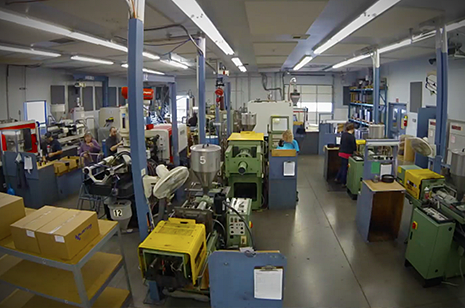
INJECTION MOULDING
Injection moulding parts and injection tools. Full solutions from design to production.
Expert Guide to Using Polycarbonate in Injection Molding ... - polycarbonate inj
Author:gly Date: 2024-10-15
Materials used in injection molding are plastics, specifically thermoplastics. There are hundreds of thermoplastics, but the most common thermoplastics used in injection molding are:
Some other common materials used for injection molding include polycarbonate, nylon, acrylic, and polyoxymethylene. Each of these materials have their advantages and disadvantages, which is why, when determining which material to work with, you need to think of how the final product will be used. Will it need to be food-safe? Does it need to be heat tolerant? UV resistant? These are some of the things you need to consider before deciding which material to use.
Once you know which material to use, you will be able to decide which material is best for your project. Specifically, you will need to choose between an amorphous plastic or a semi-crystalline plastic. The main difference between these two families of plastics is how they react to heat.
Here is a table of the most common thermoplastic materials used for injection molding with their unique features and most common applications.
To run the Draft Analysis tool in SOLIDWORKS, you will find it on the Evaluate tab of the CommandManager, or if you want to go another route, it can also be found under the drop-down menus in View > Display > Draft Analysis.
One of the most important aspects of the part design process is design for manufacturing (DFM). A good place to start, as with most things in life, is Wikipedia. It defines DFM as “the process of designing or engineering a product in order to facilitate the manufacturing process in order to reduce its manufacturing costs. DFM will allow potential problems to be fixed in the design phase, which is the least expensive phase in which to address them.”
If you hover the mouse cursor over any of the part’s faces, it will give you a dynamic update of the draft on the face you are over. Exiting the command also allows the colors to stay displayed on the part. This makes it easy for you to make any changes to the part and see the colors update as you make changes.
Thermoplastics are plastics that melt when heated and make plastic injection molding possible. Most of the plastic products used today are created using thermoplastics because of how diverse this material is. Some thermoplastics are very sturdy and rigid, while others are flexible and rubber-like. Some are clear and others are opaque. It is this diversity that makes thermoplastics such an appealing material for manufacturers.
For more organic shaped parts, you may want to call upon the gradual transition option, which uses a gradient display rather than discrete colors.
Amorphous materials shrink or expand less when heated or cooled because they don’t have a sharp melting point, making the process more forgiving and gradual. Unlike amorphous plastics, semi-crystalline plastics have a much sharper melting point and are known to expand or contract a great deal more when exposed to changing temperature extremes.
I’m making plastic pliers. mostly needle nose pliers. What material should I use, I don’t need strong heat or chemical resistance in the material used. They should not generate static charges, but they should be electrically non conductive.
In our first of three blog posts, let’s take a look at some useful design checks available in SOLIDWORKS for injection molding.
Ideal thickness for injection-molded parts varies on material but can be anything from 0.5mm to 25mm, but most engineering plastics fit between approximately 1mm and 4mm.
Couldn’t have said it better myself. Should be pretty straightforward, right? Well, form can often compete with function and design compromises have to be made when factoring in business decisions. Furthermore, the more complex your design become, the more taxing it is to check that every feature is fit to manufacture.
Luckily, the accessibility of 3D CAD in recent years has brought a multitude of checking tools to “spell check” your design based on DFM rules. Note that specific guidelines such as recommended draft angles or wall thickness are manufacturer dependent. But using these tools can reduce manufacturing costs, a lot of back and forth with the shop floor, time to market, and even save your reputation as a good engineering designer.
Tough Black (Loctite Henkel 3843) and Ceramic-Filled (BASF 3280) are two new advanced photopolymer materials now available for 3D printing.
Mark Rushton is a product portfolio manager for SOLIDWORKS, in the Desktop products team, focused on additive manufacturing. He has been involved with 3D CAD and 3D printing for over 15 years in several capacities from research to consulting for the likes of Rolls Royce, GE, JCB, and Dyson.
The blog “Materials Used in Injection Molding” provides a comprehensive overview of the various materials suitable for injection molding processes. The author effectively discusses the properties and applications of common plastics, such as ABS, polypropylene, and polycarbonate, highlighting their strengths and limitations. This information is crucial for professionals in the industry who need to make informed decisions about material selection for specific applications. Thank you for sharing this valuable resource, and I look forward to more informative posts that delve deeper into material science and its impact on manufacturing!
The third check in SOLIDWORKS for injection molding is Undercut Analysis. More undercuts mean a more complex multipart tool rather than a simple two-piece tool. More complexity means more added expense and manufacturing time because of features like side-actions. Undercut Analysis is right beneath Draft Analysis and once again, select the pull direction for the option to use the adjustment triad if you haven’t explored all possibilities yet. To make it easier to see these undercut faces, you can toggle the display of each type of face by clicking the hide/show Eye icon next to each face type.
SOLIDWORKS will then highlight positive draft in green, faces requiring draft in yellow, and negative draft in red (assuming they are all set to default colors). When viewing the part from both sides of the direction of pull, it should be all green from one side and all red from the other. Any yellow faces, need draft added.
When you run it, you need to tell SOLIDWORKS the direction of pull and what angle of draft you want to look for as acceptable. In most situations, 2 degrees is the amount to look for. For shut offs or if there is a texture required on the face, you should apply at least 3 degrees.
These three thermoplastic materials are used all the time. They are cost-effective, durable, and can tolerate the stresses of constant use. You likely use products made from these three materials often, if not every day. For example, ABS is the thermoplastic used to make your keyboard and parts of your phone.
Of course, if you want to really be sure your injection-molded part is going to successfully be manufactured, go one stage further and simulate it with SOLIDWORKS Plastics. This will highlight many more things all at once versus running individual checks, so running design checks with a full injection mold simulation is the best approach—especially if you want to get your design right early in the development process.
Proto Labs, Inc. 5540 Pioneer Creek Dr. Maple Plain, MN 55359 United States P: 877-479-3680 F: 763-479-2679 E: [email protected]
Our digital factories create prototypes and low-volume parts fast, while our manufacturing network, offers advanced capabilities and volume pricing.
The first thing you want to check for is draft. Without that, parts are not going to eject from the mold cleanly and easily. The molding process is typically engineered around speed and volume so the easier the parts come out, the faster they can be produced and the less chance those parts will incur any cosmetic defects.
Our helpful design aid demonstrates part features that are too thin or too thick, bad bosses, right and wrong ribs, and other considerations to be mindful of while designing parts for injection molding.
Do you need design-for-manufacturing (DFM) assistance? Or, are you ready for production? We have a full suite of services to offer and a lifetime mold guarantee.
Check back next week for part two of our SOLIDWORKS blog series when we look at tips for improving DFM on machined parts.
Enter a value based on the overall thickness of the part (what you want the thickness to be). Choosing the Show Thin Regions will color code all the faces of the part thinner than that value. Thin walls means the flow of polymer is restricted and could cause a short shot. Choose the Show Thick Regions radio button and SOLIDWORKS will color code all faces thicker and thinner than the target value. Much like Draft Analysis, hovering the cursor over the model shows the thickness in that spot. If the walls are too thick, you could end up with sink marks or warpage.
Choosing the right material for your project will help to streamline the process, improve your product’s performance, and reduce costs.
Get machined parts anodized and chromate plated with our quick-turn finishing option. Eligible materials include aluminum 6061/6082 and 7075.
The application of the product will determine the material used. If a product needs to be transparent yet still durable, like an automobile headlight, polycarbonate would be a good choice. What if your product is a container, like a milk jug? Then polyethylene is the type of material you’ll want to use. Polyethylene is often used for food packaging because it is food safe and won’t leach chemicals.
The next consideration helps ensure the material flows nice and evenly into the mold. For this to happen, we want as close to constant wall thickness as possible. This can be especially challenging where we add bosses, clips, and ribs. To highlight any problem areas, we can call upon the Thickness Analysis in SOLIDWORKS. This is found on the Evaluate tab of the CommandManager but is also under the Tools drop-down menu.
For extra help, SOLIDWORKS can count all the faces based on whether they are positive, negative, or require draft. To do this, simply click the Face Classification box. If you are not exactly sure the angle of the direction of pull, use the adjustment triad to play around with different pull directions.


LK-Mould Ltd.,
No.15, JinShen Road, Jin xia District
Changan Town, Dongguan
523850 Guangdong
China

