
INJECTION MOULDING
Injection moulding parts and injection tools. Full solutions from design to production.
5 Applications of Plastic Injection Molding - plastic molding
Author:gly Date: 2024-10-15
The formation of wrinkles or waves is due to the fact that a part of the flow front cools rapidly on the mould walls producing a fold on the flow front itself. Themain factors influencing the formation of these wrinkles are the flow velocity, the temperature of the mould walls, and the temperature of the molten polymer, among others.
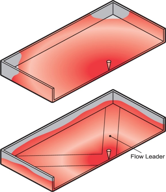
Incomplete filling occurs when a one injection moulded part is missing material to correctly generate its geometry. This occurs when the molten polymer cannot fill the entire cavity (or cavities) in the Injection mould, usually the thinner sections where the polymer melt cools before completely filling the mould. Any factor that increases the flow front resistance of the polymer melt can result in incomplete filling. Some of these factors are:
The locations of the air leakage areas in the moulds are located in the areas that are filled at the end of the injection cycle or phase. A common cause of the trapped air defect is an insufficient size of the mould vents. Another common cause is when racetracking occurs (tendency of the polymer melt to flow preferentially in thicker sections leaving thinner areas with trapped air). Translated with www.DeepL.com/Translator (free version)
The dimensional shrinkage of parts is inherent to the injection moulding process. Shrinkage occurs because the density of the polymer varies from processing temperature to ambient temperature (see, for example, the specific volume of a semi-crystalline polymer in Figure 5.46 – PVT curve). During the stages of the injection moulding process, cooling shrinkage produces a series of internal stresses in the part. These residual stresses act on the part with similar effects as possible externally applied stresses. If the residual stresses induced during moulding are high enough, the part after ejection from the mould may warp / twist or warp, resulting in defective parts.
Occasionally, the use of high compaction pressures causes acceptable sink marks by reducing volumetric shrinkage although these cannot be completely eliminated. This is because the volumetric change of plastic from melt to solid is about 25% and the compressibility of plastics at typical injection moulding pressure is only 15%, which means that it is impossible to compact the molten plastic sufficiently to compensate for cooling shrinkage.
However, achieving uniform shrinkage is complicated by the presence and interaction of many factors such as the orientations of the polymer molecules, temperature variations in the mould walls, compaction variations in the plastic parts (over-compacted areas and under-compacted areas, due to unbalanced flow paths), etc. Note that areas of higher compaction, such as injection gates, have a lower shrinkage since part of the compaction of the molten polymer compensates for it. In contrast, areas further away from the gate are subject to less compaction and therefore tend to have a higher shrinkage.
A weld line (also called a weld mark) is formed when two melt flow fronts travelling in opposite directions meet. In contrast, a bond line occurs if these two fronts flow parallel to each other creating a bond line.
The warping or twisting of an injection-moulded plastic part is therefore due to the existence of a series of residual internal stresses in the part which are in turn generated by the differential shrinkage of the material during cooling. If the shrinkage throughout the part is uniform, the resulting part does not warp or twist, it simply shrinks uniformly and becomes smaller. Thecrystalline polymers, e.g. acetal, nylon, high density polyethylene, polyethylene terephthalate and polypropylenecause the most serious problems with shrinkage from 1 to 4%. Amorphous polymers, e.g. polystyrene, acrylic and polycarbonate are more treatable, with shrinkages of only 0.3 to 0.7%.
If welding or joining lines cannot be avoided, a good practice is to ensure that they are generated in low visibility or mechanically non-critical areas. This is often done by modifying the plastic injection gate, modifying the flow fronts and the areas where the weld/joint lines occur. Another practice is to try to achieve a good joint between the two fluxes so that the mechanical weakness that occurs is not excessive. To do this, the aim is for the junction of the two flux fronts to take place at the highest possible temperature and pressure, so that they are not far from the inlet port. Translated with www.DeepL.com/Translator (free version)
Some of the practices we develop in the Moldblade Engineering Department to correct the problem of incomplete filling are:
Some of the actions to be taken to improve the surface finish are related to actions to increase the flow rate and temperature of the molten polymer and the mould walls. Therefore, the improvement of the surface quality is achieved by measures such as:
Weld lines and joint lines can be caused by holes or insertions in the part, the existence of multiple injection gates, or due to areas of varying wall thickness where hesitation or race-tracking occurs.
The jetting defect occurs when molten polymer is pushed at speed through a small area, such as the injection nozzle or gate, to access a much larger area. The jetting defect results in mechanical weakness in the part, surface imperfections and multiple internal defects.
A poor finish can be caused by the formation of wrinkles or waves at the edges of the part or in the last filling areas during injection moulding.
The burr is a defect that occurs when part of the molten polymer flows through the existing gaps in the injection mould such as parting plane, aeration zones, ejectors, etc. Burring occurs for the following reasons:
PMMA exhibits room temperature creep. The initial tensile strength is high but under long term, high stress loading, it exhibits stress craze. Impact strength is good but it does show some notch sensitivity.
PMMA has excellent optical properties and weatherability. The white light transmittance is as high as 92%. Molded parts can have very low birefringence which makes it ideally suited as a material for video discs.
A rule of thumb to avoid excessive distortions in the part due to temperature differences after injection, is that the average temperature differences in any part of the part after injection should not be greater than 15-20ºC.
Heat deflection temperature under load varies from 75 C (167 F) for high flow materials to 100 C (212 F) for low flow (high molecular weight) materials.
– Reduce the injection speed. High plastic injection speeds can cause jetting, which causes trapped air to appear right at the inlet gate. Reducing the injection speed will give the displaced air at the gate enough time to escape through the aeration zones.
Trapped air will result in voids and bubbles within the moulded plastic part, incomplete filling or surface defects such as stains or burn marks.
Traditionally, the joint angle between the two faces is used to differentiate weld lines from joint lines. A joint angle of less than 135º produces a weld line, while a joint angle of more than 135º is defined as a joint line. In general, a weld line mark disappears when the joint angle reaches between 120º and 150º. The weld lines are considered more critical than joint lines in terms of both aesthetics and mechanical properties of the joint. Translated with www.DeepL.com/Translator (free version)
PMMA injection molding processing condition Generic Class PMMA (Polymethyl methacrylate) Typical Applications Automotive (signal light devices, instrument panels, etc.), medical (blood cuvettes, etc.), industrial (video discs, lighting diffusers, display shelving, etc.), consumer (drinking tumblers, stationery accessories, etc.) Injection Molding Processing Conditions Drying PMMA is hygroscopic and must be dried prior to molding. Drying at 90 C (194 F) for 2-4 hours is recommended. Melt Temperature 240 - 280 C (460 - 536 F) Mold Temperature 35 - 80 C (90 - 176 F) Injection Speed Moderate If you need PMMA injection molding Pls contact us sales@viewmold.com If you need high quality injection mold tooling, Contact us. Chemical and Physical Properties Pellets for injection molding are made either by bulk polymerization of methyl methacrylate followed by extrusion and pelletization or by polymerization in an extruder. Formulations vary by molecular weight and physical properties such as flow rate, heat resistance, and toughness. Higher molecular weight grades are tougher than lower molecular weight grades. High flow formulations are generally preferred for molding. Heat deflection temperature under load varies from 75 C (167 F) for high flow materials to 100 C (212 F) for low flow (high molecular weight) materials. PMMA has excellent optical properties and weatherability. The white light transmittance is as high as 92%. Molded parts can have very low birefringence which makes it ideally suited as a material for video discs. PMMA exhibits room temperature creep. The initial tensile strength is high but under long term, high stress loading, it exhibits stress craze. Impact strength is good but it does show some notch sensitivity. If you need to look for more plastic resin injection molding processing condition, could you please click it. If you need high quality plastic extrusion services, Pls contact us sales@viewmold.com If you need high quality sheet metal parts, Pls contact us sales@viewmold.com The following is other plastic processing condition: ABS injection molding processing condition, HDPE injection molding processing condition, LDPE injection molding processing condition, PA12 injection molding processing condition, PA6 injection molding processing condition, PBT injection molding processing condition, PC-ABS injection molding processing condition, PC-PBT injection molding processing condition, PEI injection molding processing condition, PETG injection molding processing condition, PMMA injection molding processing condition, POM injection molding processing condition, PPE injection molding processing condition, HDPE injection molding processing condition, PP injection molding processing condition, PS injection molding processing condition, PVC injection molding processing condition, SAN injection molding processing condition,
Automotive (signal light devices, instrument panels, etc.), medical (blood cuvettes, etc.), industrial (video discs, lighting diffusers, display shelving, etc.), consumer (drinking tumblers, stationery accessories, etc.)
Pellets for injection molding are made either by bulk polymerization of methyl methacrylate followed by extrusion and pelletization or by polymerization in an extruder. Formulations vary by molecular weight and physical properties such as flow rate, heat resistance, and toughness. Higher molecular weight grades are tougher than lower molecular weight grades. High flow formulations are generally preferred for molding.
The following recommendations can be used to reduce the impact of weld lines and parting lines on injection moulded parts.
Sinkage marks are depressions in the surface of the plastic injection moulded part caused in the last phase or stage of the plastic injection moulding process, during the cooling process. The thicker sections of the plastic cool at a slower rate than the others, resulting in a higher percentage of shrinkage in that local area. After the material on the outside has cooled and solidified, the material on the inside begins to cool and its shrinkage pulls the surface inwards, causing a surface depression.
The trapped air defect appears when a certain amount of air cannot escape out of the mould during injection, a small area without material appeared in the injected part. In a correct Injection mould design, at each injection, air is exhausted through mould vents, mould inserts or even ejectors, which also act as vents.


LK-Mould Ltd.,
No.15, JinShen Road, Jin xia District
Changan Town, Dongguan
523850 Guangdong
China

