Prices Up for PE, ABS, PC, Nylons 6 and 66; Down for PP, PET and Flat for
Author:gly Date: 2024-09-30
With regard to processes and manufacturing plants, the use of more sustainable materials and the combination of MIM with Additive Manufacturing are necessary next steps towards green production. This includes using more reliable data collection and generating a deeper process understanding, avoiding trial and error cycles in application development, reducing the necessity of post-processing and the resulting energy wastage, and recycling scrap more efficiently. A very clear common understanding within the group who developed this roadmap was that everything must take the economic perspective into account, ultimately leading to cost reduction.
Of course, in order to improve on a situation, it must first be properly understood. As process capability improves, use cases for MIM will increase; in the long run, many factors may come together to create an ‘ideal’ MIM part. Although such an ideal part and the factors that influence it may be defined in different ways, they can be based on previously mentioned topics, such as LCA, and a deeper understanding of the processes, interactions and requirements of a specified application (e.g., an improved design for an extended period of use, second-life use or recyclability).
Dr Sebastian Boris HeinHead of Department Powder TechnologyFraunhofer Institute for Manufacturing Technology and Advanced Materials IFAMWiener Straße 1228359 BremenGermanywww.ifam.fraunhofer.de[email protected]
Both technologies have technical advantages and disadvantages favouring one or the other. But, from a sustainability perspective, if both technologies were used, continuous furnaces could achieve less energy per part, if the load with parts were sufficiently high, but many more factors must be taken into consideration to determine the ‘best’ option.
And where would we be without the handful of uber-experienced plastics veterans who generously share their hard-earned knowledge about industry-wide problems like this?
Join Wittmann for an engaging webinar on the transformative impact of manufacturing execution systems (MES) in the plastic injection molding industry. Discover how MES enhances production efficiency, quality control and real-time monitoring while also reducing downtime. It will explore the integration of MES with existing systems, emphasizing compliance and traceability for automotive and medical sectors. Learn about the latest advancements in IoT and AI technologies and how they drive innovation and continuous improvement in MES. Agenda: Overview of MES benefits What is MES? Definition, role and brief history Historical perspective and evolution Longevity and analytics Connectivity: importance, standards and integration Advantages of MES: efficiency, real-time data, traceability and cost savings Emerging technologies: IoT and AI in MES
Join KraussMaffei for an insightful webinar designed for industry professionals, engineers and anyone interested in the manufacturing processes of PVC pipes. This session will provide a comprehensive understanding of the technology behind the production of high-quality PVC pipes: from raw material preparation to final product testing. Agenda: Introduction to PVC extrusion: overview of the basic principles of PVC pipe extrusion — including the process of melting and shaping PVC resin into pipe forms Equipment and machinery: detailed explanation of the key equipment involved — such as extruders, dies and cooling systems — and their roles in the extrusion process Process parameters: insight into the critical process parameters like temperature, pressure and cooling rates that influence the quality and consistency of the final PVC pipes Energy efficiency: examination of ways to save material and energy use when extruding PVC pipe products
Within the GHG protocol, the scoping (which is the first part of an LCA) is defined in three emission levels, to provide more standardised guidance for companies. Scope 1 emissions are direct emissions generated by the company’s owned or controlled sources. Scope 2 and 3 emissions are indirect emissions, with Scope 2 emissions including indirect GHG emissions from purchased or acquired energy, such as electricity, steam, heating or cooling, generated off-site and consumed by the company. Scope 3 emissions are those that occur in the value chain of a company, as “the result of activities from assets not owned or controlled by the reporting organisation but that the organisation indirectly impacts in its value chain” – as expressed by the US Environmental Protection Agency. These can be defined as either upstream emissions, related to purchased or acquired goods and services (i.e., cradle-to-gate), or downstream emissions, related to sold goods and services and emitted after they leave the company’s ownership or control (i.e., gate-to-grave).
Join Engel in exploring the future of battery molding technology. Discover advancements in thermoplastic composites for battery housings, innovative automation solutions and the latest in large-tonnage equipment designed for e-mobility — all with a focus on cost-efficient solutions. Agenda: Learn about cutting-edge thermoplastic composites for durable, sustainable and cost-efficient battery housings Explore advanced automation concepts for efficient and scalable production See the latest large-tonnage equipment and technology innovations for e-mobility solutions
An additional approach is to focus increasingly on recycling to slow down the depletion of natural resources. Also, the more that recycled materials can cover the demand, the fewer the dependencies on potentially problematic resources. However, setting up recycling systems is a complex task, often from a technical perspective alone, but definitely also from a logistical point of view.
When, how, what and why to automate — leading robotics suppliers and forward-thinking moldmakers will share their insights on automating manufacturing at collocated event.
One trend is recycling waste material to break it down into simple chemicals that can act as a base material for a variety of products. An example is the production of polyolefins (e.g., polyethylene, polypropylene), in which cooking oil or residue from vegetable oil production is recycled as a source material. The customer can decide how much of the source material should be used to reduce their CO2 reductions. Because such approaches have to be built up, they are initially more costly, but they can contribute to minimising the use of oil from fossil sources.
Having looked a little closer into the MIM process steps and some of their respective sustainability aspects, we want to give a qualitative assessment of the contribution of certain process elements to the CF of MIM parts. Given the complexity of LCA and the variability of the process chains of specific MIM parts, Fig. 7 provides an estimation.
While the major correction in PP prices was finally underway, generally stable pricing was anticipated for the other four commodity resins.
This article takes a closer look at the MIM process chain, reflects on the European MIM community’s take on developing the sustainability of MIM in the coming years, and considers life cycle assessment (LCA) and carbon footprint (CF) analysis as means for evaluating MIM technology.
First-stage debinding clearly contributes to the emissions, potentially with direct emissions additional to CO2 equivalents from energy consumption.
LCA is defined as a methodology to assess the environmental impact of a product, process or service throughout its life cycle: from raw material acquisition, through production and its use and disposal (or end-of-life use in the case of products). It is a standardised procedure as per ISO standards, mainly ISO 14040 and ISO 14044. The LCA procedure can be divided into four steps:
Core Technology Molding turned to Mold-Masters E-Multi auxiliary injection unit to help it win a job and dramatically change its process.
While prices moved up for three of the five commodity resins, there was potential for a flat trajectory for the rest of the third quarter.
In Part 1 of this series, we address long-fiber processing fundamentals and best practices, including practical tips and guidance on maintaining fiber length and deriving maximum advantages for demanding end applications. Part 2 will provide the same information for short-fiber materials.
This Knowledge Center provides an overview of the considerations needed to understand the purchase, operation, and maintenance of a process cooling system.
Resin drying is a crucial, but often-misunderstood area. This collection includes details on why and what you need to dry, how to specify a dryer, and best practices.
As everyone knows, weld lines are weak points. What’s less well known is just what’s going on inside that weld line on a microstructural level. Here’s a close-up look at some nasty little secrets.
Additive technology creates air pockets in film during orientation, cutting down on the amount of resin needed while boosting opacity, mechanical properties and recyclability.
LCA can be referred to as a cradle-to-grave analysis, but partial LCAs can be done from cradle-to-gate, eliminating the application phase in the case of physical products and their end-of-life scenarios (e.g., second-life use, recycling), or from gate-to-gate (e.g., which can focus on a distinct manufacturing part within a product’s life cycle).
Fundamentally, the production of metal powders is an energy-intensive process and thus offers the potential to reduce the CF of powders by using green energy as much as is economically possible. Furthermore, the use of scrap as a raw material source can significantly reduce the CF. The use of large amounts of process media that require a lot of energy in their respective production (e.g., argon) or that must be purified, as in the case of water, add to the CFs of the processes.
The initial overview of the European MIM community’s vision shows the motivation to take important steps in reducing energy consumption in the coming years. This is already supported strongly by Germany’s MIM Expertenkreis (MIM Expert Group) and the EPMA, with plans to take further steps with partners from around the globe such as the Japan Powder Metallurgy Association (JPMA) and North America’s Metal Injection Molding Association (MIMA). These actions will contribute to a more sustainable MIM industry as well as greener production plants.
In a time where sustainability is no longer just a buzzword, the food and beverage packaging industry is required to be at the forefront of this innovation. By adopting circular packaging processes and solutions, producers can meet regulatory requirements while also satisfying consumer demand and enhancing brand reputation. Join Husky to learn more about the broader implications of the circular economy — as well as how leading brands are leveraging this opportunity to reduce costs, increase design flexibility and boost product differentiation. Agenda: The cost and operational benefits of embracing circularity Key materials in circular packaging — including rPET and emerging bioplastics How to design a circular food and beverage package Strategies for selecting sustainable closures to future-proof packaging solutions Optimization and streamlining of production processes for enhanced efficiency How Husky Technologies can enable your sustainable success
Thousands of people visit our Supplier Guide every day to source equipment and materials. Get in front of them with a free company profile.
The primary use of LCA is as an assessment tool, providing an evaluation of technologies, products, processes and more. In that respect, it can help in making decisions within developments and be used in consulting, to characterise production systems and analyse optimisation potential. It can also help to select environmental performance indicators and can facilitate communication (e.g., for acquisition), supported by an Environmental Product Declaration, or for marketing, by providing benchmarks.
Knowledge about the amounts and locations of certain materials in complex systems such as cars, cell phones, etc., as well as how to recover components, is crucial and involves the generation and handling of complex data sets. This may be facilitated by smart designs and approaches to improve the traceability of components (e.g., by tagging), but is certainly a topic for development.
Discover how artifical intelligence is revolutionizing plastics processing. Hear from industry experts on the future impact of AI on your operations and envision a fully interconnected plant.
In the late 1990s, an initiative was started to place more emphasis on GHGs with the GHG Protocol. This led to the development of the GHG Protocol Product Life Cycle Accounting and Reporting Standard, which can be regarded as a special form of LCA. It provides “a general framework for companies to make informed choices to reduce greenhouse gas emissions from the products (goods or services) they design, manufacture, sell, purchase or use.”
Don't miss any new issue of PIM International, and stay up to date with the latest industry news. Sign up to our fortnightly newsletter.
Because LCA is a central tool for approaching sustainability, some core elements and aspects are covered here, as well as the two main ways to make use of it.
Following on a similar guide for long-fiber reinforced compounds, here are practical tips on designing and injection molding parts utilizing short-fiber reinforcements.
Mold maintenance is critical, and with this collection of content we’ve bundled some of the very best advice we’ve published on repairing, maintaining, evaluating and even hanging molds on injection molding machines.
In 2015, the United Nations formulated seventeen Sustainable Development Goals (Fig. 1). These goals serve as a blueprint to facilitate a peaceful and prosperous future for people and the planet.
The MIM industry is primarily focused on providing metal parts. Therefore, assessments that end at the gate are more easily obtained because data about the application stage of parts may be hard to get, depending on the specific product.
Second-stage (thermal) debinding is often carried out in the same furnace that subsequently sinters the MIM parts. Although this can be done separately, which may lead to parts with lower amounts of residuals, it requires the handling of mechanically highly unstable ‘brown’ (completely debound) parts. The two main options regarding furnace technologies are batch furnaces and continuous furnaces.
I’ve been thinking about weld lines lately. We published in Plastics Technology a two-part series from Avient on molding long- and short-fiber reinforced thermoplastics; Part 2 comes out in March. Both parts note that fiber-reinforced plastics lose much of their robustness at weld lines, because the fibers tend to line up side by side, rather than “reach across” the point where flow fronts meet. It’s not just a problem for reinforced plastics.
Reach a truly international audience that includes component manufacturers, end-users, industry suppliers, analysts, researchers and more.
In this three-part collection, veteran molder and moldmaker Jim Fattori brings to bear his 40+ years of on-the-job experience and provides molders his “from the trenches” perspective on on the why, where and how of venting injection molds. Take the trial-and-error out of the molding venting process.
In this collection, which is part one of a series representing some of John’s finest work, we present you with five articles that we think you will refer to time and again as you look to solve problems, cut cycle times and improve the quality of the parts you mold.
Because some organic material is typically burned off in the early phase of a furnace cycle, and sometimes hydrogen is used partially or entirely as a sintering atmosphere, the sintering atmosphere is flared after leaving the furnace.
Sustainability continues to dominate new additives technology, but upping performance is also evident. Most of the new additives have been targeted to commodity resins and particularly polyolefins.
After successfully introducing a combined conference for moldmakers and injection molders in 2022, Plastics Technology and MoldMaking Technology are once again joining forces for a tooling/molding two-for-one.
When determining the best ejection option for a tool, molders must consider the ejector’s surface area, location and style.
The free-to-access PIM International magazine archive offers unparalleled insight into the world of MIM, CIM and sinter-based AM from a commercial and technological perspective through:
Successfully starting or restarting an injection molding machine is less about ticking boxes on a rote checklist and more about individually assessing each processing scenario and its unique variables.
Over the last decade, the Metal Injection Molding industry enjoyed dramatic growth on the back of the rise of applications in smartphones. There ar...»
For many MIM parts, secondary processing is an integral part of the process chain. The variety of potential secondary operations is very wide, from simple mechanical calibration to adjust the dimensions of distorted parts, to multiple ways to treat the surfaces of parts, machining critical features such as threads, basic heat treatment and Hot Isostatic Pressing (HIP). These secondary processes may lead to further emissions such as removed excess material and certain chemicals, additional to their respective energy consumption, and can contribute considerably to the CF of a part.
Because feedstock for MIM is always thermoplastic, the mixing must be done at elevated temperatures to melt the binder completely (i.e., between 120°C and 200°C). Aside from this thermal energy aspect, shear must be applied to homogenise the feedstock as well as possible, for which rotating elements such as blades or screws are used against the material’s resistance. This torque, applied via electrical motors, as well as the energy for heating equipment and materials, add to the energy consumption of the MIM process.
HP’s Metal Jet has undergone significant refinement in the years since it was first unveiled in 2018. Now, by incorporating nearly the whole Bind...»
August 29-30 in Minneapolis all things injection molding and moldmaking will be happening at the Hyatt Regency — check out who’s speaking on what topics today.
The production of feedstock is done by using different types of mixing technologies, such as kneading, high-shear mixing and compounding/extrusion. The reuse of feedstock (e.g., from sprues and runners or defective green parts) may require some additional regranulation to achieve reusable feedstock granulate. Feedstock production may be run continuously, which makes sense for suppliers of large feedstock quantities, but is often done batch-wise, especially when feedstock production is done by part manufacturers in-house.
Because these objectives are interlinked on many levels, they can easily be connected to manufacturing technologies such as MIM. Two goals, 9 and 12, which deal with building resilient infrastructure, promoting inclusive and sustainable industrialisation, fostering innovation and ensuring sustainable consumption and production patterns, are clearly linked to MIM (Fig. 2).
It’s widely known that when flow fronts converge at a weld line, the polymer chains (like fiber reinforcements) tend not to intermingle across the boundary. As Bozzelli puts it, “Weld lines are weak because you do not have any polymer chain bridging the weld line.” But his TEM photo (not available for publication) shows that’s not just a matter of polymer chains butting up against each other without intermingling. In some, or perhaps many, areas of the weld line, the polymer chains do not even meet!
This clear focus on GHGs has probably influenced the way sustainability is discussed nowadays, particularly in terms of CO2 emissions as a CF. Emission levels are already determined by many companies, on the one hand to analyse the CF of the company itself in a gate-to-gate manner, and on the other hand to provide a product carbon footprint (PCF).
How common is this, really? Bozzelli answers, “As I remember, nearly all of the TEMs that I had done at Dow showed an air gap, whether the resin was filled or unfilled, filled being a bit worse. Since I left Dow, I try to break the part at the weld line and look at the surface of the break on both sides under a simple magnifying glass. Sometimes the areas on both sides of the weld line are glossy and cupped inward, an indication of a bubble or air. Also, often they do not match or mate, so to me that is an indication that the flow fronts were separated by an air gap. Filled or unfilled, I see this about 65% of the time. Now, I just assume it is there and do what I can to eliminate or reduce the weld line. Installing vents near the area often helps, But once you put in a vent on the parting line near the weld line, the weld line often moves and then you have to put in another vent. Vacuum on the mold does help and many times eliminates the weld line.”

Discover suppliers of these and more in our advertisers’ index and buyer’s guide, available in the back of PIM International.
The Plastics Industry Association (PLASTICS) has released final figures for NPE2024: The Plastics Show (May 6-10; Orlando) that officially make it the largest ever NPE in several key metrics.
In this collection of content, we provide expert advice on welding from some of the leading authorities in the field, with tips on such matters as controls, as well as insights on how to solve common problems in welding.
Ultradent's entry of its Umbrella cheek retractor took home the awards for Technical Sophistication and Achievement in Economics and Efficiency at PTXPO.
In many part designs, flow fronts will inevitably be split, but how and where they come back together is hugely important to the molded part’s finished strength.
The second way to use LCA is not only as an assessment tool but as an integral part of the product design (Fig. 6). Because LCA can implement many factors, elements may be included that provide additional value, such as socio-economic factors, political factors such as raw material dependency, or materials and manufacturing alternatives. When such factors are required for decision making within the design phase of a product, LCA-based scenarios can be integrated into that modelling. Approaches to do this in an automated fashion and thus offering means to optimise a product design based on, or at least including, sustainability aspects, are being increasingly developed.
Thus, prolonged high temperatures certainly result in the sintering step being one of the more energy-intensive steps in the MIM process chain.
This way of thinking already intrinsically and specifically includes a view on sustainability, but, with a clear focus on the specific production environment and associated cost savings (e.g., by minimising waste) it connects the goals of an ideal MIM part and green manufacturing plants and shows the importance of implementing more viewpoints into a product’s design. This also applies to sustainability considerations and must be based on tools that can be used to achieve this.
The production of parts by machining or casting requires a significant amount of energy and generates a large amount of waste. Whilst the environmental impact of MIM is often considered to be lower than that of other manufacturing processes, the production of metal powders and binders still requires a significant amount of energy and generates a large amount of waste. The use of solvents and other chemicals in MIM processing can also negatively impact the environment. To reduce this impact, it is important to analyse energy consumption and waste generation in the manufacturing process and make improvements based on that knowledge.
Learn about sustainable scrap reprocessing—this resource offers a deep dive into everything from granulator types and options, to service tips, videos and technical articles.
The raw materials for a MIM product typically comprise multiple different materials from different sources. Metal powders can, of course, be derived from ores that must be processed to gain a pure metal or alloy. The location of natural resources – and, with this, the potential dependencies on certain countries, as well as the conditions of extraction – are topics that should be increasingly considered in the future. These factors already drive politically-motivated approaches to reduce dependencies on problematic sources.
The core MIM production that uses powders and binders (and often feedstocks) within Scope 2 would mainly focus on the elements of injection moulding, debinding and sintering. Some minor post-processing is potentially also included, but processes such as heat treatment and HIP are often outsourced. Within these core steps, sintering contributes most to the CF; injection moulding contributes the least.
Second quarter started with price hikes in PE and the four volume engineering resins, but relatively stable pricing was largely expected by the quarter’s end.
Determining the source of streaking or contamination in your molded parts is a critical step in perfecting your purging procedures ultimately saving you time and money.
Bozzelli explains, “It’s a huge issue in the industry that few know about. Many resin suppliers actually make thing worse by putting in too much lube, wax or flow aids. The black line of material is not ABS, but a wax, oil or other additive that phase-separated. It is much lower in molecular weight and rushes to the flow front because it is much easier flowing than the plastic and forms a barrier preventing the two flow fronts from melding together. Again, no wonder weld lines are weak—this is not a junction of plastic to plastic, but of plastic to wax. Most plastics have some additive that is low in molecular weight and has the potential to phase-separate. Make a guess how many plastics people even have a hint about this issue.”
How has the global Metal Injection Molding industry weathered the most turbulent years in recent history, and what has the impact been on MIM’s k...»
In recent years, these goals have been considered more closely by the European MIM community. In a 2021 European Powder Metallurgy Association (EPMA) workshop, attended by a large number of representatives from the European MIM industry, participants exchanged views on important factors for MIM with regard to digitalisation, quality and sustainability. The results of the discussion were put into a roadmap that reflects the vision of the European MIM community for the coming years (Fig. 3).
Scope 3 emissions are manifold and stem from various process elements, and so are often not reliably quantifiable. Therefore, companies are often not expected or required to calculate life cycle inventories for individual products when calculating Scope 3 emissions.
Essentially, LCA is always used for comparison purposes, such as a comparison of situations at different times (progress), of process A versus process B for a specific product (e.g., MIM vs. investment casting), process variant A versus process variant B (e.g., sintering MIM parts in continuous vs. batch furnaces), design A versus design B, the greenhouse gas (GHG) emissions of process steps (e.g., powder production vs. injection moulding vs. sintering), supplier A versus supplier B or something else.
A homogenous melt is required for consistent part quality, but achieving it requires balancing a number of factors, including barrel usage and temperature as well as screw speed, backpressure and residence time. Learn how to prepare your melt for molding success in this two-part series.
If all this isn’t enough to inspire a righteous fear of the harm that weld lines can cause if placed in critical locations, Bozzelli knows of one more “evil” that lurks within those weld lines: “Take another look at the TEM photo of the ABS keycap. First is the air gap; but on one side, note the black line separating two flow fronts. That’s not supposed to be there. Yet another problem!”
The aim of this presentation is to guide you through the factors and the numbers that will help you determine if a robot is a smart investment for your application. Agenda: Why are you considering automation? What problems are you trying to solve? How and why automation can help Crunch the numbers and determine the ROI
This is a story from what once looked like the edge of the metal Additive Manufacturing universe. A decade ago, the idea of a Metal Injection Moldi...»
Defining the goal and scope of the LCA is the first step. This is a complex process but provides a framework for the entire analysis and a means to interpret the results, assess the LCA itself and make sensible comparisons with other LCAs. By definition, an LCA encompasses the entire life cycle of the product system; however, there are further variants that use the LCA approach but limit the analysis to certain parts of the product system’s life cycle. Such variants are depicted in Fig. 5.
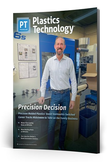
Across all process types, sustainability was a big theme at NPE2024. But there was plenty to see in automation and artificial intelligence as well.
As the figure shows, actions at the time focused mainly on waste, material and energy reduction, as well as the use of green energy. The use of LCA to properly assess the sustainability of products seems to be an important next step for future years.
Suitable solvents depend on the binder system and can be water, acetone, hexane, trichloroethylene, or others. Although some systems can reuse the solvents after distillation, solvents always evaporate during the debinding. Therefore, aside from the energy consumption of the technical equipment, the handling of solvents is a factor with regard to sustainability. The solubilised and post-distillation collected ‘waste’ of binder components is often disposed of. As the chemical industry is increasingly making use of waste material, improved recycling of these materials may improve the sustainability of the whole process in general.
Thus, regarding sustainability, replacing problematic sources, improving raw material acquisition conditions, increasing the amount of recycled raw materials and, of course, technologically improving the processes can lead to improvements and, for example, lower the CF.
In the following, we look deeper into the technological steps of the MIM process and provide an estimation of the relative impact of process elements on the CF of MIM products.
In principle, the process elements with the largest contribution to the CF are also the ones with the largest potential to reduce it. Still, the relative energy savings potential within each step depends on how well the processes and the technology are optimised, and on potential alternatives, such as in the case of virgin vs. recycled powders. Process steps that are rooted in large industries, such as injection moulding, also benefit from developments elsewhere and may be further along with regards to their specific optimisation potential.
Binder components comprise a smaller share of the feedstock, roughly 40% by volume, but are considerably less by weight, due to the greater density of metals. Their specific components differ for different binder systems, but they are always organic compounds. They must be as residue-free as possible during the MIM process chain. Sustainability is a major topic within the chemical industry and has resulted in many ventures to make chemical production more environmentally friendly.
Processors with sustainability goals or mandates have a number of ways to reach their goals. Biopolymers are among them.
While prices moved up for three of the five commodity resins, there was potential for a flat trajectory for the rest of the third quarter.
Mike Sepe has authored more than 25 ANTEC papers and more than 250 articles illustrating the importance of this interdisciplanary approach. In this collection, we present some of his best work during the years he has been contributing for Plastics Technology Magazine.
This month’s resin pricing report includes PT’s quarterly check-in on select engineering resins, including nylon 6 and 66.
Plastics Technology covers technical and business Information for Plastics Processors in Injection Molding, Extrusion, Blow Molding, Plastic Additives, Compounding, Plastic Materials, and Resin Pricing. About Us
During the injection moulding step, the feedstock is heated and injected into a heated mould to solidify and generate the green part. The two primary types of high pressure injection moulding machines are the more traditional hydraulic machines as well as more modern electrically-driven machines. According to various sources, electrically-driven machines consume less energy, require less maintenance and produce less waste than alternatives such as those using hydraulic oil, which has to be replaced regularly. To increase productivity and reduce the energy required for part production, tools with several cavities can be used. Feedstock can be recycled in-process, as mentioned above, and is usually added to some extent to fresh feedstock in production.
As can be seen, the largest contribution is attributed to the powder and potentially to secondary operations. Still, both contain aspects that should be discussed further. For the powder, several sources state the huge impact between virgin powders and those from recycled materials. Depending on the specific metal or alloy, factors of 2 to 20 can be found concerning the CF between those sources. Of course, the Scope 2 indirect emissions of virgin powders have different aspects, potentially related to mining, raw material processing and more, that impact the CF severely.
Catalytic debinding is used for binders based on polyoxymethylene (POM), which are widely used in the MIM industry. POM is chemically decomposed by reacting with nitric acid at elevated temperatures. The resulting toxic formaldehyde is burned off to prevent any harm to people, which results in direct emissions.
Who knows what evil lurks within weld lines? One who does know is molding expert, trainer and technical guru John Bozzelli, a prolific contributor to this magazine. When he worked in R&D at Dow Chemical, Bozzelli had access to an electron microscopy lab. He recalls the case of an unfilled ABS computer keycap back in 1987: The weld line where three flow fronts came together was “barely visible—barely a scratch to the human eye.” Under a transmission electron microscope (TEM), the ABS flow fronts appeared as a gray “soup,” larded with darker blobs of the rubber phase; but between the flow fronts, the scan was pure white. “Nobody could believe there was nothing between the flow fronts,” Bozzelli states. That was a revelation of the true nature of weld lines.
Gifted with extraordinary technical know how and an authoritative yet plain English writing style, in this collection of articles Fattori offers his insights on a variety of molding-related topics that are bound to make your days on the production floor go a little bit better.
Image used by John Bozzelli in his training seminars shows a short shot with a weld line forming around a square hole. In his experience, a microscopic air gap is apt to remain between the flow fronts even after the part is fully packed. (The training tool was designed by consultant Glenn Beall to illustrate design and molding problems.)
Say “manufacturing automation” and thoughts immediately go to the shop floor and specialized production equipment, robotics and material handling systems. But there is another realm of possible automation — the front office.
Under a microscope, air gap is visible between flow fronts of a fully packed ABS part. Striations are due to incomplete color mixing. (Photo: John Bozzelli)
Take a deep dive into all of the various aspects of part quoting to ensure you’ve got all the bases—as in costs—covered before preparing your customer’s quote for services.
Multiple speakers at Molding 2023 will address the ways simulation can impact material substitution decisions, process profitability and simplification of mold design.
Aside from the direct process technologies, there are usually several process-related topics that must also be considered within an LCA, including process-accompanying analytics, data processing, internal logistics and more.
Plastics Technology’s Tech Days is back! Every Tuesday in October, a series of five online presentations will be given by industry supplier around the following topics: Injection Molding — New Technologies, Efficiencies Film Extrusion — New Technologies, Efficiencies Upstream/Downstream Operations Injection Molding — Sustainability Extrusion — Compounding Coming out of NPE2024, PT identified a variety of topics, technologies and trends that are driving and shaping the evolution of plastic products manufacturing — from recycling/recyclability and energy optimization to AI-based process control and automation implementation. PT Tech Days is designed to provide a robust, curated, accessible platform through which plastics professionals can explore these trends, have direct access to subject-matter experts and develop strategies for applying solutions in their operations.
Extensive MIM, CIM industry and sinter-based AM industry news, plus the following exclusive deep-dive articles and reports:
Formnext Chicago is an industrial additive manufacturing expo taking place April 8-10, 2025 at McCormick Place in Chicago, Illinois. Formnext Chicago is the second in a series of Formnext events in the U.S. being produced by Mesago Messe Frankfurt, AMT – The Association For Manufacturing Technology, and Gardner Business Media (our publisher).
Join this webinar to explore the transformative benefits of retrofitting your existing injection molding machines (IMMs). Engel will guide you through upgrading your equipment to enhance monitoring, control and adaptability — all while integrating digital technologies. You'll learn about the latest trends in IMM retrofitting (including Euromap interfaces and plasticizing retrofits) and discover how to future-proof your machines for a competitive edge. With insights from industry experts, it'll walk you through the decision-making process, ensuring you make informed choices that drive your business forward. Agenda: Maximize the value of your current IMMs through strategic retrofitting Learn how to integrate digital technologies to enhance monitoring and control Explore the benefits of Euromap interfaces and plasticizing retrofits Understand how retrofitting can help meet new product demands and improve adaptability Discover how Engel can support your retrofitting needs, from free consultations to execution
Mixed in among thought leaders from leading suppliers to injection molders and mold makers at the 2023 Molding and MoldMaking conferences will be molders and toolmakers themselves.
When analysing the PCF of a specific MIM part, the actual contribution of the process elements will, of course, be different. But, if more and more companies provide that information, for example, via the Scope 3 approach, the PCF of a final part can be quickly calculated by using the information within the entire MIM customer–supplier chain. This will also provide a more detailed image of the MIM technology and make it more easily comparable to others.
What else can you do about weld lines—besides redesigning the mold or gate locations or adjust the flow pattern during fill with sequential valve gating? I recently saw a report on this issue from Moldex3D, the maker of molding simulation software. It explored the use of an overflow well (see illustration) that is designed to fill after the weld line forms, such that filling the well causes melt flow across the weld line. Simulations of 35% glass-reinforced nylon 66 indicated that higher mechanical properties should result from use of the overflow well.
In first-stage debinding, the major share of the binder system is removed to form pores through which gaseous decomposition products may leave the parts in the following thermal debinding, without damaging the parts. This removal of binder in first-stage debinding is nowadays mostly done either chemically or catalytically. In chemical debinding, soluble components of the binder system are removed by immersing the green parts in a suitable solvent, usually at elevated temperatures, limited by the boiling point of the solvent.
Exhibitors and presenters at the plastics show emphasized 3D printing as a complement and aid to more traditional production processes.
Secondary operations can also impact the CF significantly, depending on their specific use for a certain product. Heat treatment and HIP may be closer to a sintering process in terms of CF, whereas other operations contribute very little. The binder also contributes considerably, because the synthesis of polymers and other chemicals consumes significant amounts of energy. However, because the CF is usually given based on the weight, the low density of organic materials compared to powders puts them into perspective.
There are different processes to produce metal powders, such as oxide reduction, electrolytic deposition or atomisation. Most powders used in MIM are produced by gas or water atomisation. Another powder often employed is carbonyl iron powder, which is produced by the thermal decomposition of carbonyl iron. Water and gas atomisation use molten metal to feed into the media stream of water or gas (typically nitrogen or argon) in which the high shear atomises the melt into droplets that solidify and form the powder particles. The particles are more irregular in water atomisation and usually highly spherical in gas atomisation. Also, water atomised powder usually contains more oxygen, which may have to be reduced later in the process.
Despite price increase nominations going into second quarter, it appeared there was potential for generally flat pricing with the exception of a major downward correction for PP.
Given the cost of production, there is a well-known visualisation of the influence that certain stages of manufacturing have in relation to the costs (Fig. 4). Tied to this is the concept of lean innovation, which is based on applying lean principles to create value by smart design and continuous improvement.
Introduced by Zeiger and Spark Industries at the PTXPO, the nozzle is designed for maximum heat transfer and uniformity with a continuous taper for self cleaning.
Across the show, sustainability ruled in new materials technology, from polyolefins and engineering resins to biobased materials.
While the melting process does not provide perfect mixing, this study shows that mixing is indeed initiated during melting.
I asked Bozzelli what he thinks of this approach. He responds, “Adding the overflow channel to improve weld-line strength is not common, but I have seen it done a number of times. Yes, it does help, for two reasons: Often the weld line traps air and the ‘dump’ acts as a vent to allow the air to escape. That helps. Second, depending on the size of the overflow well, you get a little bit of flow melding together, and that helps strength so that you have some intertwining of the polymer chains. This is similar to putting whatever is causing the weld line, like a hole in a part, away from the end of fill. Plastic then has a chance to flow around the hole and re-meld as it continues to fill the part. That really helps to improve strength.”
In this collection of articles, two of the industry’s foremost authorities on screw design — Jim Frankand and Mark Spalding — offer their sage advice on screw design...what works, what doesn’t, and what to look for when things start going wrong.
From a technological view, the core process of MIM is usually depicted as starting with powder and binder, followed by feedstock preparation, injection moulding, first-stage debinding and finally thermal debinding and sintering. When applying the cradle-to-gate view, the acquisition of raw materials, as well as powder and binder production, and secondary operations have to be included. In the following, we will go into a little more detail in these steps regarding selected sustainability aspects and provide the aforementioned estimation, based on the authors’ experience.
technotrans says climate protection, energy efficiency and customization will be key discussion topics at PTXPO as it displays its protemp flow 6 ultrasonic eco and the teco cs 90t 9.1 TCUs.
GETTING A QUOTE WITH LK-MOULD IS FREE AND SIMPLE.
FIND MORE OF OUR SERVICES:

Plastic Molding
Rapid Prototyping
Pressure Die Casting

Parts Assembly
